
ELE-210 · Lesson 1 of 12 · 23 min
Digital systems and number systems
Almost every electronic product made today is a digital system at heart. A phone, a car's engine controller, a hearing aid, a traffic signal, a pacemaker and the servers in a data centre all store information as patterns of two values and process it with circuits that obey simple, exact rules. Digital logic design is the study of those circuits: how to describe what a circuit must do, how to build it from gates and flip-flops, how to make it small, fast and reliable, and how to check that it works. This course takes you from number systems and Boolean algebra to combinational and sequential circuits, finite state machines, timing, and the hardware description languages and programmable chips used to build real designs.
In a CEAB-accredited Canadian electrical or computer engineering program, digital logic usually comes in second year, alongside circuit analysis (ELE-202) and before microcontrollers and computer architecture. The two subjects meet constantly: circuit analysis explains the voltages and currents inside a gate, and digital logic explains what the gates do together. A professional engineer who signs off a safety controller or a medical device needs both views.
The examples follow Cedarline Controls, an invented company in Fredericton, New Brunswick, that designs controllers for traffic signals, parking garages and small industrial machines. Amara Osei is an engineer-in-training who joined Cedarline after graduating in electrical engineering. She works with Daniel Fortin, the senior hardware designer, on two projects this term: a pedestrian crossing controller for a city intersection, and a digital tachometer that counts pulses from a shaft sensor and shows the speed on a display. Each lesson uses part of one of these projects.
Analog and digital signals
An analog signal can take any value in a continuous range. The voltage from a microphone, the output of a thermocouple and the position of a dial are analog: between any two values there are infinitely many others. A digital signal takes only a small number of distinct values, and in nearly all practical systems just two. We call them 0 and 1, low and high, false and true, or off and on. A single two-valued quantity is a bit, short for binary digit.
The big advantage of using only two values is noise immunity. A real wire always carries some noise: interference from nearby signals, thermal noise, ground bounce and variations in the supply. If a signal had to represent one of a thousand levels, a little noise would turn one value into another. If it only has to be clearly low or clearly high, a large amount of noise can be tolerated, and every gate that receives the signal restores it to a clean low or high before passing it on. A digital signal can therefore travel through millions of gates and be copied any number of times without degrading, which is impossible for an analog signal.
Each logic family defines voltage ranges for the two values. For a gate powered from 3.3 V, an input below about 0.8 V is read as 0 and an input above about 2.0 V is read as 1. The output of a gate is guaranteed to be even closer to the rails, for example below 0.4 V for a 0 and above 2.4 V for a 1. The differences between the guaranteed output levels and the required input levels are the noise margins, which lesson 4 calculates. Voltages between the input thresholds are forbidden: a properly working circuit only passes through that region briefly during a transition.
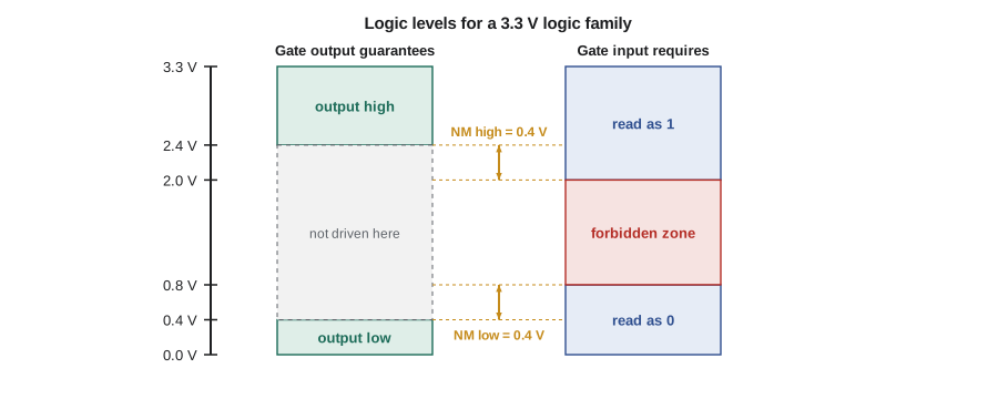
Digital systems still deal with the analog world at their edges. A tachometer's shaft sensor produces pulses that must be cleaned up into proper logic levels, and a temperature controller reads an analog sensor through an analog-to-digital converter and drives a heater through some kind of power stage. Inside, however, everything is bits.
Combinational and sequential circuits
Digital circuits come in two broad kinds. In a combinational circuit, the outputs at any moment depend only on the inputs at that moment. An adder is combinational: the sum depends only on the two numbers presented to it now. In a sequential circuit, the outputs depend on the inputs and on the circuit's history, which it remembers in storage elements called flip-flops. A counter is sequential: its next value depends on its present value. A traffic controller is sequential too, because what it does next depends on which light is on now and how long it has been on.
The course follows this split. Lessons 3 to 7 cover combinational logic: Boolean algebra, gates, simplification and the standard building blocks such as multiplexers, decoders and adders. Lessons 8 to 11 cover sequential logic: latches and flip-flops, registers and counters, finite state machines and the timing rules that make sequential circuits work. Lesson 12 shows how real designs are written in a hardware description language and built on programmable chips. This first lesson and the next deal with how numbers and other information are represented in bits, because every later lesson depends on it.
Positional number systems
We write numbers in a positional system: each digit is multiplied by a power of the base, or radix, according to its position. In the decimal number 4,705, the 4 means four thousands, the 7 means seven hundreds, the 0 means no tens and the 5 means five ones. In general, a number with digits written in base r has the value
where each digit is between 0 and r − 1. Digits to the right of the radix point have negative powers. Decimal uses base 10. Digital hardware uses base 2, binary, where the only digits are 0 and 1. Because long strings of bits are hard for people to read, designers also use base 8, octal, and much more often base 16, hexadecimal, as shorthand for binary. When the base might be unclear, it is written as a subscript or a prefix: 1011₂, 0b1011 and 0xB all describe the value eleven.
| Decimal | Binary | Octal | Hexadecimal |
|---|---|---|---|
| 0 | 0000 | 0 | 0 |
| 1 | 0001 | 1 | 1 |
| 2 | 0010 | 2 | 2 |
| 3 | 0011 | 3 | 3 |
| 4 | 0100 | 4 | 4 |
| 5 | 0101 | 5 | 5 |
| 6 | 0110 | 6 | 6 |
| 7 | 0111 | 7 | 7 |
| 8 | 1000 | 10 | 8 |
| 9 | 1001 | 11 | 9 |
| 10 | 1010 | 12 | A |
| 11 | 1011 | 13 | B |
| 12 | 1100 | 14 | C |
| 13 | 1101 | 15 | D |
| 14 | 1110 | 16 | E |
| 15 | 1111 | 17 | F |
A group of 4 bits is called a nibble and a group of 8 bits is a byte. A byte can hold 2⁸ = 256 different patterns, so as an unsigned number it ranges from 0 to 255. In general, n bits can represent 2ⁿ different values, and an unsigned n-bit number ranges from 0 to 2ⁿ − 1. This relationship appears everywhere in digital design: a 10-bit analog-to-digital converter has 1,024 output codes, a memory with 16 address lines has 65,536 locations, and a counter that must count to 1,000 needs at least 10 bits.
Converting to decimal
To convert a number from any base to decimal, multiply each digit by its positional weight and add. The binary number 101101.01 is
and the hexadecimal number 2F3 is 2 × 256 + 15 × 16 + 3 = 755. Designers soon learn the powers of two by heart: 1, 2, 4, 8, 16, 32, 64, 128, 256, 512, 1,024 and so on. Because 2¹⁰ = 1,024 is close to 1,000, the prefixes kibi (Ki), mebi (Mi) and gibi (Gi) are used for 2¹⁰, 2²⁰ and 2³⁰ when counting memory, to avoid confusion with the decimal kilo, mega and giga.
Converting from decimal
To convert a whole number from decimal to base r, divide repeatedly by r and collect the remainders: the first remainder is the least significant digit. To convert a fraction, multiply repeatedly by r and collect the integer parts: the first integer part is the most significant fractional digit. Many decimal fractions do not end in binary. The decimal fraction 0.1, for example, becomes the repeating binary fraction 0.000110011..., which is why computer programs that add 0.1 ten times do not always get exactly 1.
Worked problem
Decimal to binary for a counter limit
The tachometer counts sensor pulses in a gate time and must hold counts up to 1,000. Convert 1,000 to binary and decide how many flip-flops the counter needs.
Show solution
- Divide by 2 and keep the remainders: 1000 → 500 r0, 250 r0, 125 r0, 62 r1, 31 r0, 15 r1, 7 r1, 3 r1, 1 r1, 0 r1.
- Read the remainders from last to first: 1111101000.
- \[1111101000_2 = 512 + 256 + 128 + 64 + 32 + 8 = 1000_{10}\]
- The number has 10 bits, and 2^{10} = 1024 is the smallest power of two above 1,000.
Answer: 1,000 is 1111101000 in binary, and the counter needs 10 flip-flops, giving a range of 0 to 1,023.
The number of bits needed for a range of values is the ceiling of the base-2 logarithm. For N different values you need ⌈log₂ N⌉ bits; for a count from 0 to M you need ⌈log₂(M + 1)⌉ bits.
Hexadecimal and octal as shorthand
Because 16 = 2⁴, each hexadecimal digit corresponds to exactly four bits. To convert binary to hexadecimal, group the bits in fours starting from the radix point and replace each group with its hex digit. To convert back, replace each hex digit with four bits. Octal works the same way with groups of three, because 8 = 2³. No arithmetic is needed, which is why hexadecimal is used for memory addresses, register contents, colour codes on web pages and machine code listings.
When a datasheet says a register resets to 0x3C, Amara reads it at once as 0011 1100: bits 2, 3, 4 and 5 set, the rest clear. That fluency is worth practising until it is automatic.
# Convert between bases the way a designer does by hand
def to_base(n, base, width=0):
    digits = "0123456789ABCDEF"
    out = ""
    while n > 0:
        n, r = divmod(n, base)
        out = digits[r] + out
    return out.rjust(width, "0") or "0"

def from_base(s, base):
    value = 0
    for ch in s.upper():
        value = value * base + "0123456789ABCDEF".index(ch)
    return value

for n in (45, 255, 1000, 755):
    print(f"{n:5d} = {to_base(n, 2, 12)} (bin) = {to_base(n, 8):>4} (oct) = {to_base(n, 16):>3} (hex)")
print("0x2F3 =", from_base("2F3", 16), " 0b101101 =", from_base("101101", 2))45 = 000000101101 (bin) = 55 (oct) = 2D (hex) 255 = 000011111111 (bin) = 377 (oct) = FF (hex) 1000 = 001111101000 (bin) = 1750 (oct) = 3E8 (hex) 755 = 001011110011 (bin) = 1363 (oct) = 2F3 (hex) 0x2F3 = 755 0b101101 = 45
The function from_base uses Horner's rule: start at zero, and for each digit multiply the running value by the base and add the digit. It needs no powers at all and is how conversion is usually done in software and in hardware.
Bits, bytes and words in practice
Digital systems group bits into words of a fixed width that suits the hardware: 8 bits in a small microcontroller, 32 or 64 bits in a processor, sometimes odd widths such as 12 bits for an analog-to-digital converter or 18 bits for a memory with error checking. The bit with the highest weight is the most significant bit (MSB) and the one with weight 1 is the least significant bit (LSB). Bits are usually numbered from 0 at the LSB, so bit 7 is the MSB of a byte.
Fixed width has a consequence that every designer must keep in mind: there is a largest number. If an 8-bit unsigned counter at 255 is incremented, it wraps around to 0, and the carry out of the top bit is lost unless the circuit saves it. This overflow is not an error in the hardware; it is exactly what the circuit is built to do. Whether it is a bug depends on whether the designer planned for it. The tachometer's 10-bit counter must never be asked to count more than 1,023 pulses in one gate time, or its reading will be wrong.
| Width | Unsigned range | Typical use |
|---|---|---|
| 1 bit | 0 to 1 | A flag, an enable, one switch |
| 4 bits | 0 to 15 | One decimal digit (BCD), a nibble |
| 8 bits | 0 to 255 | A byte of data, an ASCII character |
| 10 bits | 0 to 1,023 | An analog-to-digital converter code, the tachometer count |
| 16 bits | 0 to 65,535 | Memory addresses in small systems, audio samples |
| 32 bits | 0 to about 4.29 × 10⁹ | Processor registers, network addresses |
Information that is not numbers
Bits can stand for anything, not only numbers. A group of bits can encode a letter, the state of a traffic light, a colour, an instruction for a processor or a sample of sound. The meaning lies entirely in how the designer agrees to interpret the pattern. The bit pattern 0100 0001 is the number 65, the letter A in ASCII, or perhaps a code that turns on the north-south green light in Cedarline's controller. Choosing good encodings is part of design, and lesson 2 covers the standard codes for signed numbers, decimal digits, characters and position sensors.
For the pedestrian crossing controller, Amara needs to represent the states of the intersection. There are six: main-street green, main-street yellow, all-red, side-street green, side-street yellow, and walk. Six states need ⌈log₂ 6⌉ = 3 bits, leaving two of the eight patterns unused. Lesson 10 returns to this and shows that the choice of which pattern stands for which state changes the size and speed of the circuit.
Why digital design is a discipline of its own
Digital design can look simple, since every signal is just 0 or 1. The difficulty lies in scale and timing. A modern chip contains billions of transistors, and even a small controller contains thousands of gates, so designers need systematic methods, abstraction and tools rather than intuition alone. Every signal also takes time to change, so the logical behaviour only holds if the timing rules are respected. Much of the craft lies in organizing a design into blocks that can be understood, tested and reused, and in proving that it is correct before it is built, because a mistake in a manufactured chip can cost millions to fix.
Daniel Fortin's rule for new designers at Cedarline is to describe the behaviour first, in words, a table or a state diagram, and only then draw gates or write code. The rest of this course follows that order: specify, design, simplify, implement, verify.
Common mistakes
MistakeReading a binary number from left to right when converting by repeated division.
InsteadThe first remainder is the least significant bit; read the remainders from last to first.
MistakeGrouping bits for hexadecimal from the left.
InsteadGroup in fours starting at the radix point, padding the leftmost group with zeros.
MistakeThinking n bits can count to 2ⁿ.
Insteadn unsigned bits represent 0 to 2ⁿ − 1; counting to 1,000 needs 10 bits because 2¹⁰ − 1 = 1,023.
MistakeAssuming decimal fractions always convert exactly to binary.
InsteadMany, such as 0.1, repeat forever in binary and must be rounded.
Summary and key terms
- Digital signals use two values, which gives noise immunity because every gate restores clean levels.
- Combinational outputs depend only on present inputs; sequential outputs also depend on stored state.
- In base r, each digit is weighted by a power of r; binary uses r = 2.
- Convert to decimal by summing weights; convert from decimal by repeated division (whole part) and repeated multiplication (fraction).
- Hexadecimal and octal are shorthand for binary in groups of four and three bits.
- N different values need ⌈log₂ N⌉ bits, and an n-bit unsigned word ranges from 0 to 2ⁿ − 1.
- Bit
- A binary digit, a quantity with two possible values, 0 and 1.
- Noise margin
- The difference between the voltage a gate output guarantees and the voltage a gate input requires for the same logic value.
- Combinational circuit
- A circuit whose outputs depend only on its present inputs.
- Sequential circuit
- A circuit whose outputs depend on present inputs and on stored state.
- Radix
- The base of a positional number system.
- Hexadecimal
- Base 16, written with the digits 0 to 9 and A to F; each digit stands for four bits.
- MSB and LSB
- The most significant bit (highest weight) and least significant bit (weight 1) of a word.
Practice problems
Work each problem on paper first, then reveal the answer to check.
Convert 1101 0111₂ to decimal and to hexadecimal.
Show answer
128 + 64 + 16 + 4 + 2 + 1 = 215; grouping in fours gives 0xD7.
Convert 300₁₀ to binary.
Show answer
300 = 256 + 32 + 8 + 4 = 1 0010 1100₂.
Convert 0x3C9 to binary and decimal.
Show answer
0011 1100 1001₂ = 3 × 256 + 12 × 16 + 9 = 969.
How many bits are needed to give each of 37 parking spaces a unique code?
Show answer
⌈log₂ 37⌉ = 6 bits, since 2⁵ = 32 is too few and 2⁶ = 64 is enough.
Convert 0.6875₁₀ to binary.
Show answer
0.6875 × 2 = 1.375 (1), 0.375 × 2 = 0.75 (0), 0.75 × 2 = 1.5 (1), 0.5 × 2 = 1.0 (1), so 0.1011₂.
An 8-bit unsigned register holds 250. What does it hold after adding 10, and what happened?
Show answer
260 − 256 = 4; the result overflowed and the carry out of bit 7 was lost.
Lesson quiz · 5 questions
Score 60% or more to complete this lesson.
Create a free account to save your progress, take quizzes and earn a certificate.