
ELE-210 · Lesson 10 of 12 · 23 min
Finite state machines
Counters step through a fixed sequence. Most controllers need more: their next step depends on inputs as well as on where they are. A vending machine waits for coins, a washing machine moves from fill to wash to rinse to spin depending on timers and sensors, and Cedarline's pedestrian controller moves between green, yellow, red and walk depending on a timer and the walk request. All of these are finite state machines (FSMs): sequential circuits with a finite number of states, a rule for moving between states on each clock edge, and outputs that depend on the state. FSMs are the standard way to design control logic, in hardware and in software. This lesson covers Moore and Mealy machines, state diagrams and tables, the design procedure, state encoding, and the complete pedestrian controller.
States, inputs and outputs
A state captures everything the machine needs to remember about the past in order to decide what to do next. An FSM is defined by its set of states, its inputs, its outputs, a next-state function that gives the next state from the present state and inputs, an output function, and an initial state entered at reset. In hardware, the present state is held in a register of flip-flops; the next-state function and the output function are combinational logic. On each clock edge, the register loads the next state. This is the structure described in lesson 1: combinational logic plus state held in clocked flip-flops, with the outputs computed from the state (and, in some machines, from the inputs too).
Moore and Mealy machines
There are two ways to define outputs. In a Moore machine, named after Edward Moore, the outputs depend only on the present state. Each state has a fixed set of outputs, so the outputs change only after a clock edge and are free of glitches from input changes. In a Mealy machine, named after George Mealy, the outputs depend on the present state and the present inputs, so an output can respond to an input in the same clock cycle without waiting for the next edge. Mealy machines often need fewer states, but their outputs can glitch when inputs change and they react to inputs combinationally, which can create long timing paths between machines.
In practice designers choose case by case, and many machines mix the two. Lamp outputs on a traffic controller should be Moore outputs: a traffic light must never flicker because an input changed. A signal such as 'clear the walk request now' could be a Mealy output, active in the state where the walk begins. A common compromise is to register Mealy outputs through a flip-flop, which gives a Moore-like clean output one clock later.
State diagrams and state tables
A state diagram draws each state as a circle and each transition as an arrow labelled with the input condition that causes it. In a Moore diagram, the outputs are written inside the circles; in a Mealy diagram, they are written on the arrows after a slash, as input/output. Every state must have a defined next state for every input combination; arrows that return to the same state, called self-loops, show where the machine waits. A state table holds the same information as a table, with one row per present state and columns for the next state under each input condition and for the outputs.
A first example: a sequence detector
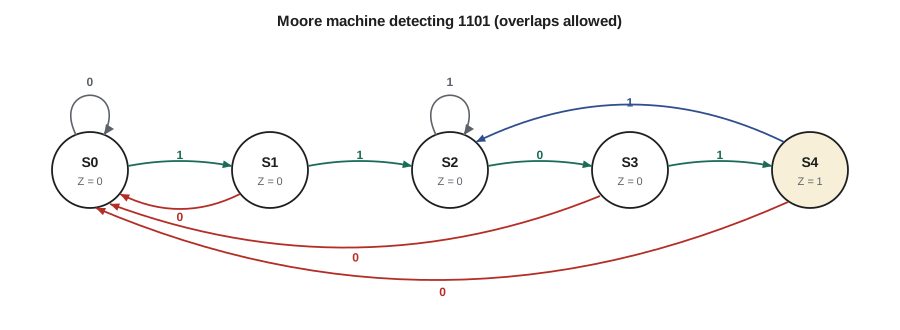
A classic exercise is a machine that watches a serial input X, one bit per clock, and raises an output Z when it sees a particular pattern. Cedarline's maintenance port uses a simple version: a technician's tool sends the pattern 1101 to unlock the configuration mode. The Moore machine needs a state for each amount of progress through the pattern: S0 (nothing useful seen), S1 (seen 1), S2 (seen 11), S3 (seen 110) and S4 (seen 1101, output Z = 1). Overlapping patterns are allowed, so after 1101, a following 101 completes the pattern again.
| Present state | Meaning | Next state if X = 0 | Next state if X = 1 | Z |
|---|---|---|---|---|
| S0 | no progress | S0 | S1 | 0 |
| S1 | seen 1 | S0 | S2 | 0 |
| S2 | seen 11 | S3 | S2 | 0 |
| S3 | seen 110 | S0 | S4 | 0 |
| S4 | seen 1101 | S0 | S2 | 1 |
The subtle entries are the ones where the pattern breaks. In S2 (seen 11), another 1 still leaves the last two inputs as 11, so the machine stays in S2. In S4, the last bit seen was a 1; a new 1 makes the last two bits 11, so the machine goes to S2. Working these out by asking 'what is the longest suffix of what I have seen that is a prefix of the pattern?' avoids mistakes.
The design procedure
Designing an FSM follows a fixed sequence of steps, and following them carefully avoids most errors.
- Understand the specification and list the inputs, outputs and what the machine must remember.
- Draw a state diagram, checking that every state has a transition for every input combination and that the reset state is marked.
- Write the state table and look for equivalent states that can be merged (states with the same outputs and the same next states for every input).
- Choose a state encoding: assign a binary code to each state.
- Write the next-state and output equations, minimize them, and decide what happens in unused codes.
- Draw the circuit or write the HDL, then simulate it against the specification, including reset and unusual input sequences.
State encoding
With k states, a binary encoding needs ⌈log₂ k⌉ flip-flops, the minimum possible. A one-hot encoding uses one flip-flop per state, with exactly one flip-flop set at a time. It needs more flip-flops, but the next-state logic is often simpler and faster, because each flip-flop's input is just the OR of the conditions that lead into its state. One-hot is common in programmable chips, which have flip-flops to spare. A Gray encoding assigns codes so that common transitions change only one bit, which can reduce power and glitches on decoded outputs. Synthesis tools can choose the encoding automatically, but the designer should know the trade-offs.
| State | Binary | Gray | One-hot |
|---|---|---|---|
| S0 | 000 | 000 | 00001 |
| S1 | 001 | 001 | 00010 |
| S2 | 010 | 011 | 00100 |
| S3 | 011 | 010 | 01000 |
| S4 | 100 | 110 | 10000 |
Whatever encoding is used, some codes may be unused: binary encoding of five states leaves three of eight codes unused, and one-hot leaves 27 of 32. In a perfect world the machine never enters them, but noise, a power glitch or a radiation hit can flip a flip-flop. A safe design makes every unused code lead back to a valid state, ideally the reset state, within a clock cycle or two. Treating unused codes as don't-cares gives smaller logic but may leave the machine stuck in a loop of illegal states. For a traffic controller that is not acceptable.
Worked problem
Next-state equations for the sequence detector
Using the binary encoding (S0 = 000, ..., S4 = 100, with bits Q2 Q1 Q0) and sending unused codes 101, 110 and 111 to S0, find the output equation and the next-state equation for Q0.
Show solution
- The output Z is 1 only in S4 = 100. Since 101 to 111 are unused, Z = Q2Q̄1Q̄0 is safest, but if unused codes are treated as don't-cares, Z = Q2.
- Q0 is 1 in S1 (001) and S3 (011). From the table, the next state is S1 when the present state is S0 and X = 1, and S3 when the present state is S2 and X = 0.
- \[Q_0^{+} = \overline{Q_2}\,\overline{Q_1}\,\overline{Q_0}X + \overline{Q_2}Q_1\overline{Q_0}\,\overline{X}\]
- Combine: =Q_0^{+} = \overline{Q_2}\,\overline{Q_0}\,(Q_1 \oplus X)
Answer: Z = Q2Q̄1Q̄0 and Q0⁺ = Q̄2Q̄0(Q1 ⊕ X); because both include Q̄2 or full decoding, unused codes do not produce false outputs.
The pedestrian crossing controller
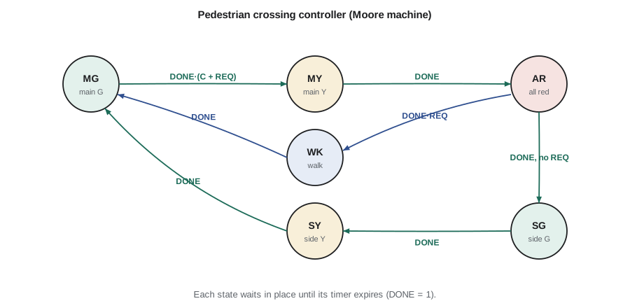
Now the main project. The intersection has a main street with heavy traffic and a side street. The specification Daniel wrote is short. Main street stays green until a car is waiting on the side street (sensor C) or a pedestrian has pressed the button (request flag REQ from lesson 8), and in any case for at least 30 s. Then main street shows yellow for 4 s, then all red for 2 s. If a pedestrian requested, the walk signal shows for 10 s with all traffic red; otherwise the side street gets green for 20 s, then yellow for 4 s. Then the controller returns to main green. A timer, built from the counters of lesson 9, is loaded with the right duration on entry to each state and raises DONE when it expires.
| State | Code | Main | Side | Walk | Timer | Leave when | Next state |
|---|---|---|---|---|---|---|---|
| MG (main green) | 000 | green | red | off | 30 s | DONE and (C or REQ) | MY |
| MY (main yellow) | 001 | yellow | red | off | 4 s | DONE | AR |
| AR (all red) | 010 | red | red | off | 2 s | DONE: REQ → WK, else SG | WK or SG |
| SG (side green) | 011 | red | green | off | 20 s | DONE | SY |
| SY (side yellow) | 100 | red | yellow | off | 4 s | DONE | MG |
| WK (walk) | 101 | red | red | on | 10 s | DONE | MG |
The walk request is cleared (ACK = 1) when the machine enters WK. Codes 110 and 111 are unused; Amara sends them to AR, the all-red state, so that a corrupted state register shows red in every direction before resuming. Daniel adds one more safety rule that does not appear in the table: an independent conflict monitor checks the lamp outputs and forces all lamps to flashing red if green is ever shown to both streets, or to a street and the walk signal, at the same time. Real traffic controllers have such monitors, separate from the main controller, because a logic or wiring fault must never produce conflicting greens.
# Simulate the pedestrian controller with a timer, one step per second
DUR = {"MG": 30, "MY": 4, "AR": 2, "SG": 20, "SY": 4, "WK": 10}
LAMPS = {"MG": ("green", "red", "off"), "MY": ("yellow", "red", "off"), "AR": ("red", "red", "off"),
         "SG": ("red", "green", "off"), "SY": ("red", "yellow", "off"), "WK": ("red", "red", "WALK")}

def next_state(s, done, car, req):
    if not done:
        return s
    if s == "MG":
        return "MY" if (car or req) else "MG"
    return {"MY": "AR", "AR": "WK" if req else "SG", "SG": "SY", "SY": "MG", "WK": "MG"}[s]

state, timer, req, car = "MG", DUR["MG"], False, False
events = {12: "button", 70: "car"}          # time in seconds -> input event
log = []
for t in range(130):
    if events.get(t) == "button":
        req = True
    if events.get(t) == "car":
        car = True                           # the loop detector stays on while the car waits
    if state == "SG":
        car = False                          # the waiting car has been served
    timer -= 1
    done = timer <= 0
    new = next_state(state, done, car, req)
    if new != state:
        if new == "WK":
            req = False                      # ACK clears the walk request
        state, timer = new, DUR[new]
        log.append(f"t={t + 1:3d}s  -> {state:2s}  main {LAMPS[state][0]:6s} side {LAMPS[state][1]:6s} walk {LAMPS[state][2]}")
print("\n".join(log))t= 30s -> MY main yellow side red walk off t= 34s -> AR main red side red walk off t= 36s -> WK main red side red walk WALK t= 46s -> MG main green side red walk off t= 76s -> MY main yellow side red walk off t= 80s -> AR main red side red walk off t= 82s -> SG main red side green walk off t=102s -> SY main red side yellow walk off t=106s -> MG main green side red walk off
The simulation shows the behaviour the specification asks for: the walk request does not cut short the main-street green, the walk phase replaces the side-street green when someone is waiting, and the side street is served when a car arrives. Before building any hardware, Amara runs many such simulations with random events and checks automatically that conflicting greens never occur, an early taste of the verification methods of lesson 12.
Implementing the controller
With the binary codes in the table, the controller needs three state flip-flops and a timer. The lamp outputs are decoded from the state bits, for example Main green = Q̄2Q̄1Q̄0 and Walk = Q2Q̄1Q0. The next-state logic takes the state bits, DONE, C and REQ as inputs: six inputs, which is already beyond comfortable hand minimization. A designer would write the state table in a hardware description language (lesson 12) and let the synthesis tool produce the logic, choosing binary or one-hot encoding to suit the target chip. The thinking, though, is all in the state diagram: once it is right, the rest is mechanical.
Equivalent states and minimization
Two states are equivalent if they produce the same outputs and, for every input, lead to equivalent next states. Equivalent states can be merged without changing the machine's behaviour, giving fewer states and possibly fewer flip-flops. A first draft of a state diagram often contains redundant states, especially when written directly from a long specification. Systematic minimization uses a partition method: start by grouping states with the same outputs, then repeatedly split groups whose members go to different groups for some input, until no group splits. Each final group becomes one state. For the controllers in this lesson the diagrams are already minimal, but the method matters for machines produced automatically from other descriptions.
Common mistakes
MistakeLeaving a state without a transition for some input combination.
InsteadCheck every state against every input combination; self-loops count.
MistakeUsing Mealy outputs to drive lamps or other visible outputs.
InsteadUse Moore outputs, or register Mealy outputs, so they cannot glitch with inputs.
MistakeForgetting overlap in a sequence detector.
InsteadAfter a match or a mismatch, go to the state for the longest suffix that is still a prefix of the pattern.
MistakeTreating unused state codes as don't-cares in a safety controller.
InsteadSend every unused code to a safe state such as all red.
MistakeStarting with gates before the state diagram is right.
InsteadGet the diagram and table right first; the logic follows mechanically.
Summary and key terms
- An FSM has a state register, next-state logic and output logic, and a defined reset state.
- Moore outputs depend only on the state; Mealy outputs also depend on present inputs.
- State diagrams and state tables describe the same machine; every state needs a transition for every input.
- Design steps: specify, diagram, table, minimize, encode, derive equations, implement, simulate.
- Binary encoding minimizes flip-flops; one-hot simplifies logic; Gray encoding reduces bit changes.
- Unused state codes should lead to a safe state, and safety-critical outputs deserve independent monitoring.
- Finite state machine
- A sequential circuit with a finite set of states and rules for moving between them on each clock edge.
- Moore machine
- An FSM whose outputs depend only on its present state.
- Mealy machine
- An FSM whose outputs depend on its present state and present inputs.
- State diagram
- A drawing of states as circles and transitions as labelled arrows.
- State encoding
- The assignment of binary codes to the states of an FSM.
- One-hot encoding
- A state encoding with one flip-flop per state, exactly one of which is set at a time.
- Equivalent states
- States with the same outputs whose next states are equivalent for every input.
Practice problems
Work each problem on paper first, then reveal the answer to check.
How many flip-flops do binary and one-hot encodings need for a 12-state machine?
Show answer
Binary: ⌈log₂ 12⌉ = 4. One-hot: 12.
In the 1101 detector, the machine is in S3 and receives 0. Where does it go and why?
Show answer
S0: the last bits are 1100, and no suffix of it is a prefix of 1101 except the empty one.
Draw the next-state rule for a Moore machine that outputs 1 when it has seen two 1s in a row.
Show answer
States A (last bit 0), B (one 1), C (two or more 1s, Z = 1): A→B on 1, B→C on 1, C→C on 1, all → A on 0.
Why are traffic lamp outputs made Moore outputs?
Show answer
They change only on clock edges and cannot glitch when inputs such as sensors change.
Write the decode equation for the side-street green lamp with the codes in the controller table.
Show answer
SG = 011, so Side green = Q̄2Q1Q0.
In the controller, a pedestrian presses the button during side-street green. When does the walk signal appear?
Show answer
After SY and a full cycle back through MG (at least 30 s), MY and AR: the request is served at the next AR.
Lesson quiz · 5 questions
Score 60% or more to complete this lesson.
Create a free account to save your progress, take quizzes and earn a certificate.