
ELE-210 · Lesson 7 of 12 · 23 min
Arithmetic circuits
Computers were built to calculate, and arithmetic circuits remain at the centre of every processor, digital signal processor and graphics chip. This lesson builds them from the gates of lesson 4 and the number formats of lesson 2. It starts with the half adder and full adder, chains full adders into a ripple-carry adder, works out its delay, and shows how carry-lookahead makes addition faster. It then turns an adder into a subtractor, adds overflow detection, builds magnitude comparators, and combines these pieces into a simple arithmetic logic unit. Multiplication and BCD addition round out the lesson.
The half adder
Adding two single bits A and B gives a 2-bit result: a sum bit S and a carry bit C. The truth table shows that the sum is 1 when exactly one input is 1, which is the exclusive-OR, and the carry is 1 only when both inputs are 1, which is the AND. A circuit that does this is a half adder. It is called half because it cannot accept a carry from a previous column, so it can only add the least significant bits.
The full adder
Every column of a multi-bit addition except the first has three inputs: the two bits to add and the carry in from the column to the right. A full adder adds A, B and a carry in Cᵢₙ and produces a sum S and a carry out Cₒᵤₜ. The sum is 1 when an odd number of inputs are 1, which is a 3-input XOR. The carry out is 1 when at least two inputs are 1, which is the majority function.
| A | B | Cin | Cout | S |
|---|---|---|---|---|
| 0 | 0 | 0 | 0 | 0 |
| 0 | 0 | 1 | 0 | 1 |
| 0 | 1 | 0 | 0 | 1 |
| 0 | 1 | 1 | 1 | 0 |
| 1 | 0 | 0 | 0 | 1 |
| 1 | 0 | 1 | 1 | 0 |
| 1 | 1 | 0 | 1 | 0 |
| 1 | 1 | 1 | 1 | 1 |
The second form of the carry shows that a full adder can be built from two half adders and an OR gate: the first half adder adds A and B, the second adds the carry in to their sum, and the carry out is 1 if either half adder produced a carry. That form also introduces two signals that the fast adders below depend on: the generate signal G = AB, which means the column produces a carry by itself, and the propagate signal P = A ⊕ B, which means the column passes an incoming carry along.
The ripple-carry adder
To add two n-bit numbers, chain n full adders: the carry out of each column feeds the carry in of the next. The carry into the least significant column is 0 for plain addition. This ripple-carry adder is simple and small, using only n full adders, and it is the right choice when speed is not critical. Its weakness is delay. In the worst case, a carry generated in the lowest column must travel through every column to reach the top, for example when adding 0111 1111 and 0000 0001, and each column adds its carry delay.
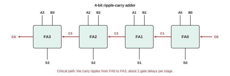
If one gate delay is t, a full adder's carry output takes about 2t after its inputs are ready (an AND level and an OR level), so an n-bit ripple-carry adder needs roughly 2nt for the final carry, plus a little more for the last sum. For 8 bits that is about 16 gate delays; for 64 bits, about 128. At typical on-chip gate delays of a few tens of picoseconds, a 64-bit ripple adder would take several nanoseconds, too slow for a processor running at gigahertz clock rates.
Carry-lookahead
The way to speed up addition is to compute the carries in parallel rather than waiting for each to ripple. Using generate and propagate, the carry out of column i is Cᵢ₊₁ = Gᵢ + PᵢCᵢ: column i produces a carry if it generates one, or if it propagates the carry coming in. Substituting each carry into the next gives every carry directly in terms of the G and P signals and the initial carry C₀.
Each carry is now a two-level sum of products, so all four carries are ready after the one gate delay needed to form G and P plus two more for the AND-OR, about 3t, no matter which column they belong to. The cost is gates with many inputs: the expression for C₄ needs a 5-input AND and a 5-input OR. That is why carry-lookahead is usually applied in groups of four bits, and the groups are combined with a second level of lookahead using group generate and group propagate signals. A 16-bit two-level lookahead adder takes roughly 5 to 7 gate delays instead of about 32.
Many other fast adders exist. Carry-select adders compute the upper half of the sum twice, once for each possible carry in, and pick the right one when the carry arrives. Prefix adders, such as the Kogge-Stone and Brent-Kung designs, compute all carries with a tree of generate and propagate combinations in about log₂ n levels and are standard in high-performance processors. All of them trade more gates and wires for less delay.
# Compare ripple-carry and 4-bit carry-lookahead carry delays (in gate delays)
def ripple_add(a, b, n, cin=0):
    carry, s, t_carry = cin, 0, 0
    worst = 0
    for i in range(n):
        x, y = (a >> i) & 1, (b >> i) & 1
        s |= (x ^ y ^ carry) << i
        new_carry = (x & y) | (carry & (x ^ y))
        # a carry that must travel through this column adds about 2 gate delays
        t_carry = t_carry + 2 if (x ^ y) and carry else 2 if (x & y) else t_carry
        carry = new_carry
        worst = max(worst, t_carry)
    return s, carry, worst

def cla_delay(n, group=4):
    # 1 delay for G/P, 2 per lookahead level, 2 more to ripple between groups (one-level CLA)
    groups = -(-n // group)
    return 1 + 2 + 2 * (groups - 1)

for a, b in [(0x7F, 0x01), (0x55, 0x2A), (0xFF, 0x01)]:
    s, c, t = ripple_add(a, b, 8)
    print(f"{a:08b} + {b:08b} = {c}{s:08b}  carry chain about {t} gate delays")
for n in (8, 16, 32, 64):
print(f"{n:2d} bits: ripple worst case about {2 * n:3d}, 4-bit-group lookahead about {cla_delay(n):2d}")01111111 + 00000001 = 010000000 carry chain about 14 gate delays 01010101 + 00101010 = 001111111 carry chain about 0 gate delays 11111111 + 00000001 = 100000000 carry chain about 16 gate delays 8 bits: ripple worst case about 16, 4-bit-group lookahead about 5 16 bits: ripple worst case about 32, 4-bit-group lookahead about 9 32 bits: ripple worst case about 64, 4-bit-group lookahead about 17 64 bits: ripple worst case about 128, 4-bit-group lookahead about 33
Subtraction and the adder-subtractor
Lesson 2 showed that A − B = A + B̄ + 1 in two's complement. An adder becomes a subtractor by inverting B and setting the carry in to 1. A single control signal SUB can do both: feed each Bᵢ through an XOR gate with SUB (which passes Bᵢ unchanged when SUB = 0 and inverts it when SUB = 1), and connect SUB to C₀ as well. When SUB = 0 the circuit adds; when SUB = 1 it subtracts. This adder-subtractor is the arithmetic core of every simple processor.
Overflow detection follows from lesson 2. For unsigned numbers, a carry out of the top column during addition means overflow; during subtraction, a carry out of 0 means a borrow occurred, so A was smaller than B. For signed numbers, overflow is V = Cₙ ⊕ Cₙ₋₁, which needs access to the carry into the top column. An adder built from full adders makes that signal available, so the overflow detector is one XOR gate.
Worked problem
Speed change on the tachometer
The tachometer subtracts the previous reading B = 0110 0100 (100) from the new reading A = 0101 0000 (80) in an 8-bit adder-subtractor. Find the result and the flags.
Show solution
- SUB = 1, so each bit of B is inverted: B̄ = 1001 1011, and C₀ = 1.
- \[0101\,0000 + 1001\,1011 + 1 = 1110\,1100\]
- There is no carry out of bit 7 (C₈ = 0), so as unsigned numbers a borrow occurred: A < B.
- The carry into bit 7 is also 0, so V = C₈ ⊕ C₇ = 0: no signed overflow.
- As a signed number, 1110 1100 = −20.
Answer: The difference is −20 (1110 1100), with no signed overflow; the speed fell by 20 counts.
Magnitude comparators
A comparator decides whether A = B, A > B or A < B. Equality is easy: two numbers are equal when every pair of bits is equal, so A = B is the AND of the XNORs of corresponding bits. Deciding which is larger works from the most significant bit down: A > B if at the highest bit position where they differ, A has a 1 and B has a 0. With the equality signals xᵢ = XNOR(Aᵢ, Bᵢ), a 4-bit comparator gives
The expression for A < B is the same with A and B swapped. Comparators can be cascaded by feeding the results of a lower-order comparator into the least significant position of a higher one. Alternatively, an adder-subtractor compares as a side effect: subtract and look at the result's sign, carry and zero flags, which is how processors implement compare instructions.
Amara uses a comparator for the tachometer's overspeed alarm. The measured count is compared with a limit stored in a register set by a technician. When the count exceeds the limit, a relay output trips. Because the alarm protects a machine, Daniel adds a second check: if the comparator and a software check disagree, the system shuts down. Redundancy like this is common in safety functions.
The arithmetic logic unit
An arithmetic logic unit (ALU) combines arithmetic and logical operations behind a function-select input. A simple 4-bit ALU might offer add, subtract, AND, OR, XOR, pass A, increment and compare, chosen by a 3-bit operation code. Internally, it computes several results in parallel, an adder-subtractor for the arithmetic and a row of gates for each logic operation, and a multiplexer picks the one the operation code asks for. It also produces status flags: zero (all result bits 0), negative (the MSB), carry and overflow. The processor's control unit sets the operation code, and its branch logic tests the flags.
| F2 F1 F0 | Operation | Result |
|---|---|---|
| 000 | Add | A + B |
| 001 | Subtract | A − B |
| 010 | AND | A · B (bitwise) |
| 011 | OR | A + B (bitwise) |
| 100 | XOR | A ⊕ B (bitwise) |
| 101 | Pass A | A |
| 110 | Increment | A + 1 |
| 111 | Compare | A − B, flags only |
Multiplication
Binary multiplication is simpler than decimal multiplication because each partial product is either zero or a shifted copy of the multiplicand: multiplying by a 1 bit copies it, and by a 0 bit gives zero. The partial products are formed with AND gates (Aᵢ AND Bⱼ) and added. A sequential multiplier uses one adder and a shift register, adding one partial product per clock cycle: small but slow, needing n cycles for n bits. An array multiplier adds all partial products at once with a grid of full adders: fast but large, needing about n² adders. Product width is the sum of the operand widths, so an 8 × 8 multiplier gives a 16-bit result. Multiplying by a constant power of two is just a shift, which costs nothing in hardware, so designers often rearrange calculations to use shifts.
Worked problem
Shift-and-add multiplication
Multiply 1011 (11) by 1101 (13) using shifted partial products.
Show solution
- Bit 0 of the multiplier is 1: partial product 1011.
- Bit 1 is 0: partial product 0000, shifted one place.
- Bit 2 is 1: partial product 1011, shifted two places: 101100.
- Bit 3 is 1: partial product 1011, shifted three places: 1011000.
- \[1011 + 101100 + 1011000 = 10001111_2 = 143\]
Answer: 11 × 13 = 143 = 1000 1111; an 8-bit product from two 4-bit operands.
BCD adders
Lesson 2 described BCD addition: add two digits in binary, and if the result exceeds 9 or carries out, add 6. In hardware this needs a 4-bit binary adder, a correction-detect circuit that computes K = C₄ + S₃S₂ + S₃S₁ (true for sums 10 to 19), and a second adder that adds 0110 when K = 1, with K becoming the decimal carry to the next digit. Chaining BCD adder stages gives a decimal adder of any length. The tachometer accumulates readings for its averaging function this way, so its display never needs a binary-to-decimal conversion.
Common mistakes
MistakeUsing a half adder in a column that receives a carry.
InsteadEvery column except the lowest needs a full adder.
MistakeAssuming ripple-carry delay is the same for every input.
InsteadThe worst case is a carry that travels the whole chain; design for the worst case.
MistakeForgetting to set the carry in to 1 when subtracting.
InsteadA − B = A + B̄ + 1: invert B and set C₀ = 1.
MistakeReading the carry out as signed overflow.
InsteadSigned overflow is Cₙ ⊕ Cₙ₋₁; the carry out matters for unsigned arithmetic.
MistakeSizing a product register the same as the operands.
InsteadAn m-bit by n-bit product needs m + n bits.
Summary and key terms
- A half adder gives S = A ⊕ B and C = AB; a full adder adds a carry in, with S = A ⊕ B ⊕ Cin and Cout the majority function.
- A ripple-carry adder chains n full adders; its worst-case delay grows linearly, about 2n gate delays.
- Carry-lookahead uses G = AB and P = A ⊕ B to compute carries in parallel, at the cost of wider gates.
- An adder-subtractor XORs B with SUB and sets the carry in to SUB; signed overflow is Cₙ ⊕ Cₙ₋₁.
- Comparators test equality with XNORs and magnitude from the most significant differing bit.
- An ALU computes several operations in parallel and selects one with a multiplexer, producing status flags.
- Half adder
- A circuit that adds two bits, giving a sum and a carry.
- Full adder
- A circuit that adds two bits and a carry in, giving a sum and a carry out.
- Ripple-carry adder
- An adder in which each column's carry out feeds the next column's carry in.
- Generate and propagate
- G = AB means a column produces a carry; P = A ⊕ B means it passes an incoming carry.
- Carry-lookahead adder
- An adder that computes carries in parallel from generate and propagate signals.
- ALU
- Arithmetic logic unit: a block that performs a selected arithmetic or logic operation and reports status flags.
Practice problems
Work each problem on paper first, then reveal the answer to check.
Add 1011 and 0110 with a ripple-carry adder, listing the carries.
Show answer
Carries C1..C4 = 0, 1, 1, 1; sum 0001 with carry out 1, i.e. 17.
Write C₂ for a carry-lookahead adder in terms of G, P and C₀.
Show answer
C₂ = G₁ + P₁G₀ + P₁P₀C₀.
Estimate the worst-case carry delay of a 32-bit ripple adder with 25 ps gates.
Show answer
About 2 × 32 × 25 ps = 1.6 ns.
Using the adder-subtractor, compute 0011 − 0101 in 4 bits.
Show answer
0011 + 1010 + 1 = 1110 = −2, with no carry out (a borrow) and V = 0.
Write the equality output of a 4-bit comparator.
Show answer
E = x₃x₂x₁x₀ with xᵢ = XNOR(Aᵢ, Bᵢ).
How many AND gates form the partial products of a 4 × 4 array multiplier?
Show answer
16, one for each pair Aᵢ Bⱼ.
Lesson quiz · 5 questions
Score 60% or more to complete this lesson.
Create a free account to save your progress, take quizzes and earn a certificate.