
DCT-230 · Lesson 9 of 12 · 19 min
Direct-to-chip cooling and coolant distribution units
Hall D does not sound like Hall A. There is no roar of perimeter units, only the hum of server fans and, in the technical galleries along each side of the hall, the steady sound of pumps. Each of its 60 racks draws about 132 kW. Most of that heat never touches the room air: it is carried away by coolant flowing through cold plates clamped onto the processors inside every server. Carmen Ortiz walks Jamal through the hall on his first day there. "Everything you learned about air still applies to the twenty percent that goes to air," she says. "The other eighty percent lives in these pipes, and the pipes are much less forgiving." This lesson covers direct-to-chip liquid cooling and the coolant distribution units, CDUs, that serve it. Safety around liquid cooling work, including coolant handling and pressure, is covered in DCT-120.
Why cold plates
An AI accelerator or a large processor can draw a kilowatt or more from a package the size of a coaster. No practical airflow can carry that heat off such a small area at the temperatures the chip needs. A cold plate solves the problem by bringing liquid into contact with the chip's lid: a block of copper with fine internal channels, pressed onto the chip with thermal interface material, through which coolant flows. Heat conducts from the chip into the copper and from the copper into the coolant, which carries it away.
Direct-to-chip systems cool the hottest components, the processors and accelerators and often the memory and voltage regulators near them, with liquid. The rest of the server, including power supplies, storage, network cards and some memory, still needs air. In Hall D roughly four-fifths of each rack's heat goes to the liquid and one-fifth to the air, which the hall's fan walls remove.
The two loops
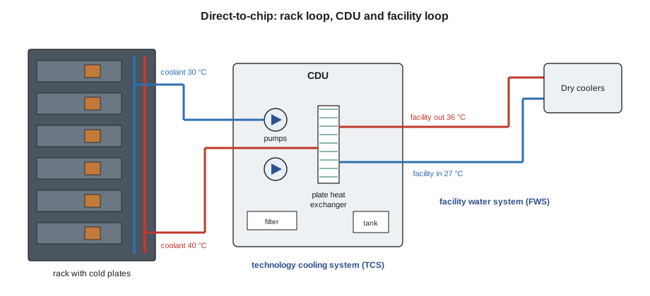
A direct-to-chip installation has two separate water loops joined by the CDU:
- The technology cooling system, TCS, also called the secondary loop: a small, clean loop that runs from the CDU through manifolds in each rack and through every cold plate, then back. It carries a specially treated coolant, often a mixture of water and about 25 percent propylene glycol, written PG25, with corrosion inhibitors. Its passages are fine, so it must be kept very clean.
- The facility water system, FWS, also called the primary loop: the building's water loop that carries heat from the CDUs to the dry coolers, towers or chillers.
The CDU contains a heat exchanger that passes heat from the TCS to the FWS without the two waters mixing, pumps that drive the TCS, a reservoir or expansion tank, filters, sensors and a controller. Keeping the loops separate protects the delicate cold plates from the dirt, scale and debris that larger building loops carry.
Inside a rack
In each Hall D rack, vertical manifolds at the back carry coolant supply and return. Each server tray connects to the manifolds with a pair of quick-disconnect couplings. Inside the tray, small hoses or tubes run to the cold plates on each processor and accelerator, often in series or parallel arrangements set by the server maker. Some racks also have small manifolds for network switches and power shelves.
The rack's manifolds connect to row piping under the floor or overhead through isolation valves and flexible hoses, as in Lesson 8. Leak detection cable runs along the bottom of the rack and under the row piping, and many racks have a drip tray at the base. Each rack's flow and temperatures are monitored, either by the CDU through sensors in the row or by the server management system reading sensors in each tray.
Temperatures and flow
Liquid cooling allows much warmer water than air cooling. The chips can run at their normal temperatures with coolant entering the cold plates at 30 °C (86 °F) or more, because the cold plate is so close to the heat. Warmer coolant means warmer facility water, which means the dry coolers can reject the heat without chillers for most of the year, and the warm return water is useful for heat recovery.
ASHRAE classifies liquid-cooled equipment by the highest facility water temperature it can accept while running at full performance. The fifth edition of the thermal guidelines names the classes by that temperature:
| Class | Facility water supply, upper limit | Typical use |
|---|---|---|
| W17 | 17 °C (62.6 °F) | Plants with chillers; cold water |
| W27 | 27 °C (80.6 °F) | Chillers or economizers |
| W32 | 32 °C (89.6 °F) | Mostly free cooling |
| W40 | 40 °C (104 °F) | Free cooling, heat recovery |
| W45 | 45 °C (113 °F) | Free cooling in hot climates, heat recovery |
| W+ | above 45 °C (113 °F) | High-temperature heat recovery |
The coolant flow through each rack is set so that the coolant warms by a planned amount, often about 10 K (18 °F), between supply and return. From the heat equation in Lesson 1, the flow needed depends on the heat to the liquid, the coolant's specific heat and density, and that temperature rise. Propylene glycol mixtures carry a little less heat per litre than plain water, so they need slightly more flow for the same job.
# Coolant flow needed per rack and per row: Q = m_dot * cp * dT
rack_kw = 132
liquid_share = 0.84               # share of the rack's heat captured by the cold plates
coolants = {"water": (998, 4180), "PG25": (1020, 3900)}   # density kg/m3, cp J/(kg K)
dt = 10                          # coolant temperature rise, K
q = rack_kw * liquid_share * 1000  # W to liquid
for name, (rho, cp) in coolants.items():
    m_dot = q / (cp * dt)              # kg/s
    lpm = m_dot / rho * 1000 * 60      # L/min
print(f"{name:6s}: {lpm:5.0f} L/min per rack, {lpm * 10:6,.0f} L/min for a row of 10")water : 159 L/min per rack, 1,595 L/min for a row of 10 PG25 : 167 L/min per rack, 1,672 L/min for a row of 10
These are the figures on Hall D's design sheets: about 170 L/min (45 gpm) per rack. The CDU serving a row of ten racks must therefore pump about 1,700 L/min (440 gpm), and the CDUs run as N+1 so that one can be serviced while the others carry the row.
Inside a CDU
Hall D's CDUs stand in the technical galleries, one for each row plus one spare per pair of rows, so that coolant equipment and its maintenance stay out of the white space. Jamal opens the front of CDU-D2B with Carmen and names the parts:
- Plate heat exchanger: a stack of thin stainless plates; TCS coolant flows on one side of each plate and facility water on the other.
- Pumps: two or more variable-speed pumps in parallel, at least one a spare.
- Filters: fine filters, often 50 microns or finer, on the TCS to keep debris out of the cold plates. A differential pressure gauge shows when they need changing.
- Reservoir or expansion tank: holds a small volume of coolant and allows for expansion as the coolant warms.
- Control valve on the facility side: varies the facility water flow to hold the TCS supply temperature at its setpoint.
- Sensors: temperatures and pressures on both sides, TCS flow, reservoir level, and often coolant conductivity or pH.
- Controller and display: shows setpoints, readings and alarms and connects to the building management system and DCIM.
The CDU's main job is to hold two things steady: the coolant supply temperature to the racks, and the pressure or flow that pushes coolant through every cold plate. It does the first with the facility-side valve and the second with its pumps.
The approach temperature
The heat exchanger can never make the TCS coolant as cold as the facility water feeding it. The difference between the facility water entering the CDU and the coolant leaving it for the racks is the CDU's approach temperature. A new, clean heat exchanger might have an approach of 2 to 4 K (4 to 7 °F). As plates foul with scale or debris, the approach grows, and the CDU must open its facility valve wider, or run with warmer coolant, to carry the same load.
# CDU approach temperature trend: coolant supply minus facility water entering
log = [  # month: (facility water in, coolant supply to racks), C
    ("Jan", 26.0, 28.5), ("Feb", 26.0, 28.8), ("Mar", 26.0, 29.2), ("Apr", 26.0, 29.7), ("May", 26.0, 30.4),
]
first = None
for month, fw_in, tcs_sup in log:
    approach = tcs_sup - fw_in
    first = first or approach
    note = "  <- schedule cleaning" if approach > 1.5 * first else ""
print(f"{month}: approach {approach:4.1f} K{note}")Jan: approach 2.5 K Feb: approach 2.8 K Mar: approach 3.2 K Apr: approach 3.7 K May: approach 4.4 K <- schedule cleaning
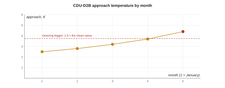
Jamal logs CDU approaches every week. A slow rise over months is a maintenance item: the heat exchanger needs cleaning at the next planned window. A sudden jump is an alarm item: something has changed, such as a valve, a strainer or a sensor.
Coolant quality
The TCS coolant protects the cold plates only if its chemistry is right. The coolant supplier and the equipment makers specify the glycol concentration, inhibitor levels, pH and limits on conductivity and particles. Open Compute Project guidance and server makers' requirements set out the tests and their intervals. The facilities team samples the coolant on a schedule and after any work that opened the loop.
Technicians never top up a TCS with ordinary water or a different coolant. Mixing coolants can make the inhibitors drop out of solution, form deposits in the cold plates and void the server warranty. Top-ups use the site's approved coolant from labelled stock, by authorized staff, and every top-up is recorded, because a loop that needs repeated top-ups has a leak.
CDU alarms and first response
CDU alarms are urgent because the chips have very little thermal margin without flow. Carmen gives Jamal the first-response card posted in each gallery:
- High coolant supply temperature: check the facility water supply temperature and flow, the facility valve position and the load. If the facility water is warm, the problem is upstream at the plant.
- Low flow or low differential pressure: check pump status and which pump is running, filter differential pressure, and any valves recently operated.
- Pump failure: confirm the standby pump has started; report at once.
- Low reservoir level: possible leak; check leak detection and the rack and row piping; do not refill without authorization.
- Leak detection alarm: go to the location, confirm, protect equipment if it can be done safely, and call the facilities team.
- Communication alarm: the CDU may still be running; check its local display.
In every case the technician tells the shift lead first, checks the Hall D rack temperatures on DCIM, and follows the authorized technician's instructions. Customers, here Corvid AI, are told through the incident process; their own engineers watch the chip temperatures in their systems and may reduce load if needed.
Worked problem
A rising approach on CDU-D2B
Jamal's weekly log for CDU-D2B shows facility water entering at 26.0 °C (78.8 °F) each week and coolant leaving for the racks at 28.5 °C (83.3 °F) in January, 29.2 °C (84.6 °F) in March and 30.4 °C (86.7 °F) in May, at about the same load. The supply setpoint is 30 °C (86 °F).
Show solution
- Calculate the approach each month: 2.5, 3.2 and 4.4 K (4.5, 5.8 and 7.9 °F).
- The approach has nearly doubled at steady load, and the coolant supply is now above its setpoint, so the CDU can no longer hold the setpoint with the facility valve fully open.
- Check the facility-side strainer differential pressure: higher than normal. Check the plate heat exchanger pressure drop: also higher.
- Report to Carmen and the facilities team with the trend; a cleaning of the facility strainer and the heat exchanger is scheduled with the spare CDU carrying the row.
Answer: A growing approach at steady load means the heat exchanger or its strainer is fouling. Trending the approach catches it before it becomes an alarm.
Common mistakes
MistakeTopping up a coolant loop with tap water.
InsteadUse only the approved coolant, by authorized staff, and record every top-up.
MistakeTreating a CDU alarm like a routine ticket.
InsteadChips have little margin without flow; tell the shift lead at once.
MistakeAssuming the facility water and rack coolant are the same water.
InsteadThey are separate loops joined by the CDU's heat exchanger.
MistakeIgnoring a slowly rising approach because there is no alarm.
InsteadA rising approach means fouling; schedule cleaning before it limits capacity.
MistakeDisconnecting a server tray's couplings to move it.
InsteadOnly trained staff disconnect liquid-cooled trays, using the server maker's procedure.
Summary and key terms
- Direct-to-chip cooling clamps cold plates on the hottest chips; the rest of the server still needs air.
- The rack coolant loop (TCS) and the building water loop (FWS) are separate, joined by the CDU.
- Coolant often enters the cold plates warm, such as 30 °C (86 °F); ASHRAE classes W17 to W+ name the facility water limits.
- Flow is set from the heat to liquid, the coolant's properties and the planned temperature rise.
- A CDU has a heat exchanger, pumps, filters, a reservoir, a facility valve, sensors and a controller.
- The approach temperature rises as the heat exchanger fouls; trend it.
- Coolant chemistry matters; only approved coolant is used, and every CDU alarm is urgent.
- Cold plate
- A metal block with internal channels, mounted on a chip, through which coolant flows.
- CDU
- Coolant distribution unit: pumps, controls and a heat exchanger serving liquid-cooled racks.
- TCS
- Technology cooling system: the secondary loop of clean coolant through the racks.
- FWS
- Facility water system: the building water loop that carries heat from the CDUs.
- PG25
- A coolant of water with about 25 percent propylene glycol and inhibitors.
- Approach temperature
- The difference between the facility water entering a CDU and the coolant it supplies.
Practice problems
Work each problem on paper first, then reveal the answer to check.
Why is the rack coolant kept separate from the building water?
Show answer
The cold plates' fine passages need clean, treated coolant; building water carries dirt and scale.
A rack sends 110 kW to liquid with a 10 K (18 °F) rise in PG25. About what flow does it need?
Show answer
About 165 L/min (44 gpm).
What does a growing CDU approach at steady load indicate?
Show answer
Fouling of the heat exchanger or a clogged strainer.
What should you check first on a CDU low-flow alarm?
Show answer
Pump status, filter differential pressure and any recently operated valves; tell the shift lead.
Lesson quiz · 5 questions
Score 60% or more to complete this lesson.
Create a free account to save your progress, take quizzes and earn a certificate.