
DCT-230 · Lesson 4 of 12 · 21 min
CRAC and CRAH units
Hall A has twelve large cabinets along its two long walls, each about the size of a garden shed laid on its side, with a display panel on the front and grilles on top. They are the hall's cooling units, and for the next week Jamal will open every one of them with Roz on the monthly preventive maintenance round. "You can't troubleshoot what you can't picture," she says, unlocking the first panel. "By Friday you'll know every part in these by name." This lesson covers the cooling units that serve air-cooled halls: what is inside them, how they are controlled, how technicians check and maintain them, and how they fail.
Two families: CRAC and CRAH
Perimeter cooling units in data halls come in two families that look almost the same from the outside:
- A computer room air conditioner, CRAC, has its own refrigeration circuit: a compressor, an evaporator coil inside the unit, and a condenser, usually outdoors on the roof or in the yard, connected by refrigerant pipes. It is a large, precise air conditioner.
- A computer room air handler, CRAH, has no compressor. Its coil is fed with chilled water from a central chiller plant. It contains fans, the coil, a control valve on the water and filters.
CRAC units are common in smaller rooms and older sites, where a central chiller plant would not pay off. CRAH units dominate in large data centres, because a central plant of large chillers, or dry coolers in a cold climate, is far more efficient than dozens of small compressors. Hall A's twelve units are CRAHs. The edge site has two small CRACs per module.
Some CRAC units use a water-cooled condenser or a pumped refrigerant economizer that lets them run without the compressor in cold weather. Technicians should read the nameplate and the site drawings rather than guess which type they are looking at.
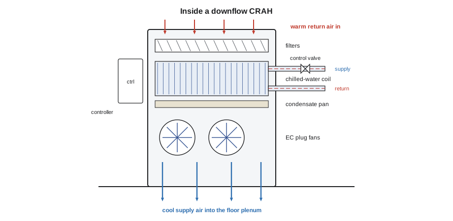
Inside a CRAH
Roz names the parts as Jamal opens the panels on unit CRAH-A04:
- Return air grille and filters: warm air from the hall enters at the top and passes through pleated filters that keep dust off the coil. Filters are rated by efficiency, commonly MERV 8 to MERV 11 for data halls.
- Chilled-water coil: rows of copper tubes with thin aluminum fins. Chilled water flows through the tubes; air passes across the fins and gives up its heat.
- Control valve and actuator: a two-way or three-way valve on the chilled-water line, opened and closed by an electric actuator to vary the water flow.
- Fans: modern units use electronically commutated, EC, plug fans whose speed can be varied smoothly. Older units have belt-driven centrifugal fans with fixed speed.
- Condensate pan and drain: catches any water that condenses on the coil and drains it away. Even units designed for sensible cooling need a working drain.
- Humidifier, if fitted: some units have a steam or ultrasonic humidifier. Many sites have disabled them.
- Controller: the unit's own computer, with a display, sensors on the return and supply air, and a connection to the building management system.
- Electrical panel: disconnect switch, fuses or breakers, fan drives and control transformer.
Air in Hall A moves down: the units are downflow units that take in warm air at the top and discharge cool air into the space under the raised floor, from which it rises through perforated tiles into the cold aisles. Upflow units, which discharge out of the top into a duct or the room, are used in rooms without raised floors.
How a CRAH is controlled
A CRAH's controller adjusts two things: how much air the fans move and how much chilled water the valve lets through the coil. Different sites control these in different ways, and technicians must know which method their site uses before changing any setting.
- Supply air temperature control: the valve opens or closes to hold the air leaving the coil at a setpoint, such as 20 °C (68 °F). This is the most common method in modern halls with containment.
- Return air temperature control: the valve holds the air entering the unit at a setpoint. Older halls use this, but it can leave the supply air too cold when loads are light.
- Rack inlet temperature control: the unit reads sensors at the racks it serves and adjusts to keep them at a setpoint. This is the closest to what matters, but needs well-placed sensors.
- Fan speed control: the fans often run to hold a pressure under the raised floor, or a pressure difference across containment, so that enough air reaches the racks without wasting fan energy.
The units also talk to each other. In Hall A, a supervisory controller shares the load among the twelve units so that all run at moderate fan speed, rather than some running flat out while others idle, and rotates which units are on standby. Fan power rises roughly with the cube of fan speed, so running all twelve units at 70 percent speed uses far less energy than running nine of them at over 90 percent.
# Fan affinity laws: the same total airflow from more units at lower speed
rated_kw = 6.5          # fan power of one CRAH at 100 % speed, kW
needed = 8.4            # total airflow needed, in "units at full speed"
print(f"{'units running':>14s} {'speed %':>8s} {'fan kW total':>13s}")
for units in (9, 10, 11, 12):
    speed = needed / units            # airflow is proportional to speed
    power = units * rated_kw * speed ** 3
print(f"{units:14d} {speed * 100:8.0f} {power:13.1f}") units running speed % fan kW total
9 93 47.6
10 84 38.5
11 76 31.8
12 70 26.8The code shows why sharing the load saves energy. The same total airflow costs far less fan power when it is spread over more units at lower speed. This is one reason a technician should not switch a standby unit off "to save energy" without understanding how the controls share the load.
Capacity and redundancy
Each unit has a rated capacity, the heat it can remove at stated air and water temperatures, given on its nameplate and in the design documents. The actual capacity on a given day depends on the chilled-water temperature, the return air temperature and the airflow. A unit fed with warmer water, or receiving cooler return air because hot and cold air are mixing, removes less heat than its rating.
Halls are designed with more cooling units than the load needs, so that one or more can fail or be switched off for maintenance without the remaining units falling short. Hall A has twelve units of 150 kW each, 1,800 kW in total, against an IT load of about 1,200 kW plus losses. That gives spare capacity even with one or two units out. The arrangement is described as N plus a number, as in N+1 or N+2, where N is the number of units needed to carry the load.
import math
# How many cooling units are needed, and how many spares the hall has
unit_kw = 150         # rated capacity of one unit, kW
units_installed = 12
it_kw = 1200
other_kw = 0.06 * it_kw   # lights, people, losses in the hall, about 6 %
load = it_kw + other_kw
n = math.ceil(load / unit_kw)
spare = units_installed - n
print(f"Heat to remove: {load:,.0f} kW")
print(f"Units needed (N): {n}; installed: {units_installed}; arrangement N+{spare}")
for out in (1, 2, 3):
    cap = (units_installed - out) * unit_kw
print(f" with {out} unit(s) out: capacity {cap:,.0f} kW, margin {cap - load:+,.0f} kW")Heat to remove: 1,272 kW Units needed (N): 9; installed: 12; arrangement N+3 with 1 unit(s) out: capacity 1,650 kW, margin +378 kW with 2 unit(s) out: capacity 1,500 kW, margin +228 kW with 3 unit(s) out: capacity 1,350 kW, margin +78 kW
The hall needs nine units to carry its heat, so it has three spares, an N+3 arrangement. With three units out the margin is small, which is why the maintenance schedule never takes more than one unit out at a time and why a unit failure during maintenance is treated as urgent.
Before Jamal takes any unit out of service for maintenance, he checks the redundancy on the shift lead's whiteboard and in the monitoring system, confirms the hall can carry the load without it, and gets permission. Taking two units down at once, or one unit down while another is already in alarm, can leave the hall short.
Monthly checks on a CRAH
Stonebridge's preventive maintenance program sets out a monthly check for each unit. Jamal works through the list on CRAH-A04:
- Read the display: setpoints, supply and return temperatures, fan speed, valve position and any active or recent alarms. Record them.
- Inspect the filters: check the pressure drop gauge or the condition of the media. Replace filters when the pressure drop reaches the replacement value or at the scheduled interval.
- Inspect the coil: look for dirt, damaged fins and signs of leaks, such as mineral deposits or stains.
- Check the condensate pan and drain: the pan should be clean and the drain clear. Pour a little water in to confirm it drains, and test the water detection sensor under the unit if the site's procedure includes it.
- Listen to the fans: unusual noise or vibration suggests a failing bearing or a loose part.
- Check the valve: compare the valve position on the display with the actuator's indicator.
- Check the chilled-water temperatures and pressures at the unit's gauges, if fitted, against the expected values.
- Look for water on the floor around and under the unit, and lift the floor tile next to it to check the subfloor.
- Close the panels, clear any alarms raised by the work, and return the unit to automatic control.
Work inside a unit is done with the unit isolated and locked out under the site's procedure, as the DCT-120 safety course covers; fans can start without warning and the electrical panel carries dangerous voltages.
Delta-T across a unit
One of the most useful numbers a technician can read is the difference between the return air temperature and the supply air temperature of a unit, its air-side delta-T. Combined with the airflow, it gives the heat the unit is actually removing. A unit with a small delta-T is doing little work, often because cold air is bypassing the racks and returning unused. A unit with a large delta-T is working hard, and may be near its limit.
The factor 1.08 in the inch-pound form combines the density and specific heat of standard air with the conversion from minutes to hours. Both forms give the same answer for the same air.
# Heat actually removed by each CRAH from its airflow and air-side delta-T
units = {  # unit: (airflow m3/s, return C, supply C)
    "CRAH-A03": (7.2, 31.0, 20.0), "CRAH-A04": (7.0, 32.4, 20.1), "CRAH-A09": (7.1, 26.0, 20.0), "CRAH-A11": (6.8, 33.0, 20.2),
}
for name, (flow, t_ret, t_sup) in units.items():
    dt = t_ret - t_sup
    kw = 1.2 * 1.006 * flow * dt
print(f"{name}: delta-T {dt:4.1f} K, heat removed {kw:5.0f} kW")CRAH-A03: delta-T 11.0 K, heat removed 96 kW CRAH-A04: delta-T 12.3 K, heat removed 104 kW CRAH-A09: delta-T 6.0 K, heat removed 51 kW CRAH-A11: delta-T 12.8 K, heat removed 105 kW
Jamal compares the units in Hall A. Most remove between 90 and 110 kW. CRAH-A09 removes only about 50 kW with its fans at the same speed as the others, because its delta-T is half theirs. Roz tells him to look for a reason: either cold air is short-circuiting back to that unit, or its return sensor is reading wrong. Lesson 7 covers how such bypass air is tracked down.
Common faults
Most CRAH problems fall into a few groups, and the display usually points to the right one:
| Symptom | Likely causes | First checks |
|---|---|---|
| High supply air temperature | Valve not opening, chilled water too warm, dirty coil | Valve position and actuator, water temperatures, coil condition |
| Low airflow alarm | Clogged filters, fan failure, belt slipping on older units | Filter pressure drop, fan status, belts |
| Water detection alarm | Blocked condensate drain, coil or valve leak, humidifier leak | Pan and drain, coil and pipe joints, humidifier |
| Unit cycling on and off | Poor control tuning, sensor fault, oversized unit at light load | Setpoints and sensor readings, trend data |
| Communication alarm | Network or controller fault | Controller power and network cable; unit may still be cooling |
CRAC units add refrigeration faults: high head pressure from a dirty or blocked outdoor condenser, low suction pressure from a refrigerant leak, and compressor trips. Refrigerant work requires a certified refrigeration technician; a data centre technician reports these alarms and does not touch the refrigerant circuit.
Worked problem
CRAH-A07 shows a high supply temperature
During his round, Jamal sees CRAH-A07 showing a supply air temperature of 26 °C (79 °F) against a setpoint of 20 °C (68 °F), with the valve shown 100 percent open and the fans at 65 percent. The neighbouring units are holding their setpoints.
Show solution
- The other units are fine, so the chilled-water supply to the hall is probably fine.
- The display says the valve is fully open. Check the actuator's own position indicator: it shows about 15 percent. The actuator is not driving the valve as commanded.
- Feel the supply and return pipes at the unit: both are about the same temperature, confirming little water is flowing.
- Check redundancy, report to the shift lead, and raise an urgent ticket for the controls contractor. The other units pick up the load in the meantime.
Answer: A failed or slipping valve actuator. The controller believed the valve was open; the actuator's own indicator showed otherwise. Comparing the command with the actual position is a basic check on any controlled valve.
Common mistakes
MistakeSwitching a standby unit off to save energy.
InsteadSpare units are part of the redundancy and the load sharing; leave controls to the supervisory system unless told otherwise.
MistakeTaking a unit out of service without checking redundancy.
InsteadConfirm with the shift lead that the hall can carry the load first.
MistakeIgnoring a unit with a small delta-T because it is not in alarm.
InsteadA small delta-T often means bypass air or a sensor fault; investigate.
MistakeOpening a unit's panels with it running.
InsteadIsolate and lock out the unit under the site procedure before working inside.
MistakeTouching the refrigerant circuit of a CRAC.
InsteadRefrigerant work needs a certified refrigeration technician.
Summary and key terms
- CRAC units have their own compressors; CRAH units use chilled water from a central plant.
- A CRAH contains filters, a chilled-water coil and valve, fans, a condensate pan and a controller.
- Units are controlled on supply, return or rack inlet temperature, with fans often on floor pressure.
- Fan power rises with roughly the cube of speed, so sharing load among more units saves energy.
- Halls have N+1 or more units; check redundancy before taking any unit out of service.
- Air-side delta-T and airflow give the heat a unit is actually removing.
- CRAC
- Computer room air conditioner: a cooling unit with its own compressor and condenser.
- CRAH
- Computer room air handler: a cooling unit with a chilled-water coil and fans.
- EC fan
- An electronically commutated fan whose speed can be varied smoothly and efficiently.
- Supply air
- The cooled air leaving a cooling unit.
- Return air
- The warm air coming back to a cooling unit.
- Fan affinity laws
- Rules relating fan speed to airflow (linear), pressure (square) and power (cube).
Practice problems
Work each problem on paper first, then reveal the answer to check.
What is the main difference between a CRAC and a CRAH?
Show answer
A CRAC has its own compressor; a CRAH uses chilled water from a central plant.
If a fan runs at half speed, about how much power does it use compared with full speed?
Show answer
About one eighth, since power varies with the cube of speed.
A unit moves 5 m³/s (10,600 cfm) with a delta-T of 12 K (21.6 °F). About how much heat does it remove?
Show answer
About 72 kW (about 247,000 BTU/h).
What should you check before taking a CRAH out of service?
Show answer
That the remaining units can carry the load, and that the shift lead has approved it.
Lesson quiz · 5 questions
Score 60% or more to complete this lesson.
Create a free account to save your progress, take quizzes and earn a certificate.