
CMPUT-229 · Lesson 5 of 12 · 32 min
Instruction set architecture and RISC-V basics
An instruction set architecture is a language with a very small vocabulary and very precise grammar. Every program a processor runs, whatever language it was written in, reaches the hardware as a sequence of instructions from this vocabulary, each encoded as a binary word. This lesson introduces the RV32I instruction set: the registers it provides and the conventions for using them, the main groups of instructions, the six formats in which instructions are encoded, how constants of any size are built from small immediates, and the pseudo-instructions that make assembly language readable. By the end you will be able to encode and decode RISC-V instructions by hand, which is the bridge between the assembly programs of lessons 6 to 8 and the processor design of lessons 9 and 10.
What an ISA specifies
An ISA defines everything a programmer or compiler can rely on: the registers and their widths; the data types and how they are laid out in memory; the instructions and exactly what each one does; the encoding of each instruction as bits; how memory is addressed; and how the processor handles exceptional events such as illegal instructions and interrupts. Just as importantly, it leaves out everything else. The RISC-V specification says what add must compute, not how many cycles it takes, how the adder is built or whether instructions run in order. That freedom is what lets a tiny microcontroller and a server processor share an ISA.
RISC-V is defined in two volumes, the unprivileged specification, which covers the instructions ordinary programs use, and the privileged specification, which covers operating-system features such as privilege modes, virtual memory and interrupt handling. The base ISAs are RV32I and RV64I, which differ in register width, plus a smaller RV32E for tiny embedded cores with 16 registers. Standard extensions are named by letters: M for multiply and divide, A for atomic operations, F and D for floating point, C for compressed instructions and V for vectors, among others. A processor's capabilities are summarized by a string such as RV32IMC or RV64GC, where G abbreviates IMAFD plus a few small extensions.
Registers and the calling convention
RV32I has 32 general-purpose integer registers, x0 to x31, each holding 32 bits, plus the program counter, which instructions cannot name directly. As lesson 4 explained, x0 always reads as zero. Apart from x0, the hardware treats all registers identically; any of them can be used for any purpose. In practice, though, separately compiled code has to agree on which registers hold arguments, which hold return values and which a called function must preserve. That agreement is the application binary interface, or ABI, and the standard RISC-V calling convention gives each register an ABI name that reflects its role. Assembly programmers almost always use the ABI names.
| Register | ABI name | Role | Preserved across calls? |
|---|---|---|---|
| x0 | zero | Hardwired zero | (constant) |
| x1 | ra | Return address | No |
| x2 | sp | Stack pointer | Yes |
| x3 | gp | Global pointer | (not allocated) |
| x4 | tp | Thread pointer | (not allocated) |
| x5–x7 | t0–t2 | Temporaries | No |
| x8 | s0 / fp | Saved register or frame pointer | Yes |
| x9 | s1 | Saved register | Yes |
| x10–x11 | a0–a1 | Arguments and return values | No |
| x12–x17 | a2–a7 | Arguments | No |
| x18–x27 | s2–s11 | Saved registers | Yes |
| x28–x31 | t3–t6 | Temporaries | No |
The distinction between saved and temporary registers is the heart of the convention. A function may freely overwrite the t and a registers, so a caller that needs a value in one of them after a call must save it first. The s registers belong to the caller: a function that wants to use one must save its old value and restore it before returning. Lesson 7 works through the consequences in detail. Note also that a7 has a special role in this course's programs: by the RARS convention, it holds the number of the system service requested by ecall.
Why 32 registers? Registers are the fastest storage in the machine, so more registers mean fewer slow memory accesses. But each register number costs encoding bits: with 32 registers, each register field needs 5 bits, and an instruction naming three registers uses 15 of its 32 bits for them. More registers also make the register file larger and slower. Thirty-two is the compromise most RISC designs reached; x86-64 has 16 general-purpose registers, and Arm's 64-bit ISA has 31.
The main groups of instructions
RV32I instructions fall into a handful of groups. Arithmetic and logic instructions, such as add, sub, and, or, xor, sll, srl, sra, slt and sltu, operate on two registers and write a third. Most have an immediate form ending in i, such as addi and andi, in which the second operand is a constant in the instruction; there is no subi, because addi with a negative constant does the job. Loads (lb, lh, lw, lbu, lhu) and stores (sb, sh, sw) move data between registers and memory, addressing memory as a base register plus a 12-bit signed offset. Conditional branches (beq, bne, blt, bge, bltu, bgeu) compare two registers and jump to a PC-relative target if the condition holds. Unconditional jumps, jal and jalr, implement procedure calls and returns. Finally lui and auipc build large constants and PC-relative addresses, and a few system instructions, such as ecall for requesting operating-system services, complete the base set.
That is the whole of RV32I apart from a few instructions for memory ordering and system control: about forty instructions. Compare that with x86-64, whose instruction count runs well over a thousand once its extensions are included. The small base is deliberate. RISC-V's designers followed principles summarized by David Patterson and John Hennessy, two of the architects behind the original RISC research: simplicity favours regularity, smaller is faster, and good design demands good compromises.
Instruction formats
Every RV32I instruction is exactly 32 bits long, and every one uses one of six formats. Keeping the formats few and regular makes decoding fast and simple, which helps every implementation from the smallest to the largest. In all formats, the lowest seven bits are the opcode, which identifies the format and the broad class of instruction. Where they exist, the destination register rd is always in bits 7 to 11, the first source rs1 in bits 15 to 19 and the second source rs2 in bits 20 to 24. Fixing the register fields in the same places means the processor can start reading registers before it has even finished working out what the instruction is.
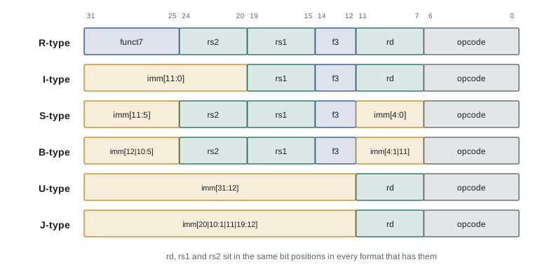
| Format | Used by | Immediate |
|---|---|---|
| R | Register–register arithmetic: add, sub, sll, slt, and … | None; funct7 and funct3 select the operation |
| I | Immediate arithmetic, loads, jalr, ecall | 12 bits, sign-extended: −2,048 to 2,047 |
| S | Stores: sb, sh, sw | 12 bits split into two fields so that rs2 stays in place |
| B | Conditional branches | 13-bit even offset (bit 0 implied zero): ±4 KiB |
| U | lui, auipc | 20 bits placed in the upper part of the register |
| J | jal | 21-bit even offset: ±1 MiB |
The S, B and J formats look odd at first: their immediates are split into pieces and, in B and J, the bits are shuffled. The reason is the rule above. Stores have two source registers and no destination, so the immediate bits that would have gone where rd sits elsewhere take that space instead. Branches have the same shape as stores, but because branch targets are always even, bit 0 of the offset is not stored, and the remaining bits are arranged so that each immediate bit lands in the same instruction position across as many formats as possible. That reduces the wiring needed to extract immediates in hardware, at the cost of making hand decoding a little fiddly.
The LLVM assembler can show the encoding of any instruction. Below, each instruction is shown with its 32-bit encoding in hexadecimal and binary; reading the binary from the right, you can find the 7-bit opcode, then rd, funct3, rs1 and so on. The option that turns off aliases makes the assembler print every instruction in its basic form.
add  a0, a1, a2
sub  a0, a1, a2
addi t0, t0, -1
lw   a5, 8(sp)
sw   ra, 12(sp)
beq  a0, zero, 16
lui  a0, 0x12345
jal ra, 2048add a0, a1, a2 0x00c58533 00000000110001011000010100110011 sub a0, a1, a2 0x40c58533 01000000110001011000010100110011 addi t0, t0, -1 0xfff28293 11111111111100101000001010010011 lw a5, 8(sp) 0x00812783 00000000100000010010011110000011 sw ra, 12(sp) 0x00112623 00000000000100010010011000100011 beq a0, zero, 16 0x00050863 00000000000001010000100001100011 lui a0, 74565 0x12345537 00010010001101000101010100110111 jal ra, 2048 0x001000ef 00000000000100000000000011101111
Worked problem
Encoding an R-type instruction by hand
Encode add a0, a1, a2.
Show solution
- add is R-type with opcode 0110011, funct3 000 and funct7 0000000.
- a0 is x10, a1 is x11 and a2 is x12, so rd = 01010, rs1 = 01011 and rs2 = 01100.
- Fields from bit 31 down: funct7 0000000 | rs2 01100 | rs1 01011 | funct3 000 | rd 01010 | opcode 0110011.
- Concatenate: 0000 0000 1100 0101 1000 0101 0011 0011.
- In hexadecimal: 0x00C58533.
Answer: add a0, a1, a2 encodes as 0x00C58533, matching the assembler output above. sub differs only in funct7, which is 0100000, giving 0x40C58533.
Decoding works the other way: extract the opcode to learn the format, then pull out the fields with shifts and masks, exactly the technique of lesson 2. The following decoder handles a useful subset of RV32I. It reassembles the scrambled branch immediate bit by bit, which is the fiddliest part.
REG = ['zero','ra','sp','gp','tp','t0','t1','t2','s0','s1','a0','a1','a2','a3','a4','a5',
       'a6','a7','s2','s3','s4','s5','s6','s7','s8','s9','s10','s11','t3','t4','t5','t6']

def sext(v, bits):
    return v - (1 << bits) if v >> (bits - 1) else v

def decode(w):
    op, rd, f3 = w & 0x7F, (w >> 7) & 31, (w >> 12) & 7
    rs1, rs2, f7 = (w >> 15) & 31, (w >> 20) & 31, w >> 25
    if op == 0x33:
        name = {(0, 0): 'add', (0, 32): 'sub', (7, 0): 'and', (6, 0): 'or', (2, 0): 'slt'}[(f3, f7)]
        return f'{name} {REG[rd]}, {REG[rs1]}, {REG[rs2]}'
    if op == 0x13 and f3 == 0:
        return f'addi {REG[rd]}, {REG[rs1]}, {sext(w >> 20, 12)}'
    if op == 0x03 and f3 == 2:
        return f'lw {REG[rd]}, {sext(w >> 20, 12)}({REG[rs1]})'
    if op == 0x23 and f3 == 2:
        imm = sext(((w >> 25) << 5) | rd, 12)          # imm[11:5] and imm[4:0]
        return f'sw {REG[rs2]}, {imm}({REG[rs1]})'
    if op == 0x63:
        imm = ((w >> 31) << 12) | (((w >> 7) & 1) << 11) | (((w >> 25) & 63) << 5) | (((w >> 8) & 15) << 1)
        name = {0: 'beq', 1: 'bne', 4: 'blt', 5: 'bge'}[f3]
        return f'{name} {REG[rs1]}, {REG[rs2]}, {sext(imm, 13)}'
    if op == 0x37:
        return f'lui {REG[rd]}, 0x{w >> 12:X}'
    return f'(not handled: 0x{w:08X})'

for w in (0x00C58533, 0x40C58533, 0xFFF28293, 0x00812783, 0x00112623, 0x00050863, 0xFE051EE3, 0x12345537):
print(f'0x{w:08X} {decode(w)}')0x00C58533 add a0, a1, a2 0x40C58533 sub a0, a1, a2 0xFFF28293 addi t0, t0, -1 0x00812783 lw a5, 8(sp) 0x00112623 sw ra, 12(sp) 0x00050863 beq a0, zero, 16 0xFE051EE3 bne a0, zero, -4 0x12345537 lui a0, 0x12345
The seventh word, 0xFE051EE3, decodes as a bne with a negative offset: a backward branch, the kind every loop ends with. Its sign bit, bit 31 of the instruction, is the sign of the offset, which is why the B-type format puts imm[12] there: sign extension can begin before the rest of the immediate is assembled.
Immediates and large constants
A 12-bit immediate covers −2,048 to 2,047, enough for most constants in real programs, but addresses and many constants are larger. RISC-V builds a 32-bit constant in two instructions. lui (load upper immediate) places a 20-bit immediate in the upper 20 bits of a register and zeros the lower 12. An addi then adds the lower 12 bits. There is one catch: addi sign-extends its immediate, so if bit 11 of the desired constant is 1, the addi effectively subtracts 4,096, and the lui value must be one larger to compensate. Assemblers handle this automatically through the li (load immediate) pseudo-instruction and the %hi and %lo operators.
Worked problem
Building 0x12345FFF
Find a lui and addi pair that loads 0x12345FFF.
Show solution
- The low 12 bits are 0xFFF. As a signed 12-bit immediate, 0xFFF is −1.
- addi will therefore subtract 1, so lui must load 0x12345FFF + 1 = 0x12346000.
- lui takes the upper 20 bits: 0x12346, which is 74,566 in decimal.
- lui a0, 0x12346 gives 0x12346000; addi a0, a0, −1 gives 0x12345FFF.
Answer: lui a0, 0x12346 followed by addi a0, a0, −1. The assembler output below confirms that li produces exactly this pair.
auipc (add upper immediate to PC) works like lui but adds the upper immediate to the address of the auipc instruction itself. Followed by an addi or a load, it reaches any address within ±2 GiB of the current instruction, which is how position-independent code finds its data: the program can be loaded at any address because the offsets between its code and data stay the same. The la (load address) pseudo-instruction expands to auipc plus addi.
Pseudo-instructions
Assembly programmers write many instructions that do not exist in the hardware. The assembler translates these pseudo-instructions into one or more real instructions, usually by exploiting x0. mv rd, rs becomes addi rd, rs, 0; nop becomes addi x0, x0, 0; not becomes xori with −1; ret becomes jalr x0, 0(ra); beqz becomes beq with x0. Pseudo-instructions make code readable without enlarging the ISA, a good example of software and hardware sharing the work. The following listing asks the assembler to translate each line and shows the real instructions that result.
li   a0, 0x12345FFF
li   a1, -5
mv   a2, a1
not  a3, a2
neg  a4, a2
seqz a5, a0
bnez a0, 12
bgt  a0, a1, 8
j    16
call helper
ret
nopli a0, 0x12345FFF => lui a0, 74566 ; addi a0, a0, -1 li a1, -5 => addi a1, zero, -5 mv a2, a1 => addi a2, a1, 0 not a3, a2 => xori a3, a2, -1 neg a4, a2 => sub a4, zero, a2 seqz a5, a0 => sltiu a5, a0, 1 bnez a0, 12 => bne a0, zero, 12 bgt a0, a1, 8 => blt a1, a0, 8 j 16 => jal zero, 16 call helper => call helper ret => jalr zero, 0(ra) nop => addi zero, zero, 0
| Pseudo-instruction | Meaning | Real instruction(s) |
|---|---|---|
| li rd, imm | Load a constant | addi, or lui + addi |
| la rd, label | Load an address | auipc + addi |
| mv rd, rs | Copy a register | addi rd, rs, 0 |
| not rd, rs | Invert all bits | xori rd, rs, −1 |
| neg rd, rs | Negate | sub rd, x0, rs |
| beqz, bnez rs, label | Branch if zero, not zero | beq, bne with x0 |
| bgt, ble rs, rt, label | Branch if greater, less or equal | blt, bge with operands swapped |
| j label | Jump | jal x0, label |
| call label | Call a procedure | auipc + jalr, or jal ra |
| ret | Return | jalr x0, 0(ra) |
Note that call is the one line printed unchanged. The assembler cannot finish it yet, because helper is defined elsewhere and its distance is unknown, so in the object file it becomes an auipc and jalr pair with a note, called a relocation, asking the linker to fill in the offset; the linker may later relax the pair to a single jal if the target turns out to be close. Lesson 8 shows the relocation in a real object file.
Fixed length, compression and other ISAs
Fixed 32-bit instructions make decoding easy but waste space: many instructions could fit in 16 bits. The RISC-V C extension adds 16-bit encodings for the most common instructions, such as c.addi, c.lw and c.mv, which can be mixed freely with 32-bit ones; the lowest two bits of each instruction tell the processor which length it is. Typical programs shrink by 25 to 30 per cent, which matters for embedded systems with little memory and for instruction cache efficiency in large ones. Nearly every Linux-capable RISC-V processor implements C.
x86-64 takes the opposite approach: its instructions are from 1 to 15 bytes long, with optional prefix bytes, opcode bytes, addressing-mode bytes and immediates. That gives dense code and great flexibility, at the cost of complex decoders that must find instruction boundaries before they can decode several instructions per cycle. Arm's 64-bit ISA, AArch64, uses fixed 32-bit instructions like RISC-V but has more addressing modes and keeps a condition-flags register. MIPS, the RISC ISA used in many textbooks before RISC-V, is close to RV32I in spirit; the main differences are details such as MIPS's branch delay slot, an instruction after each branch that always executes, which RISC-V's designers deliberately avoided because it complicates modern pipelines.
Common mistakes
MistakeForgetting that addi sign-extends its immediate when building a constant with lui and addi.
InsteadIf bit 11 of the constant is 1, add one to the lui value, or let the li pseudo-instruction work it out.
MistakeWriting subi or any other instruction that does not exist.
InsteadUse addi with a negative constant; RV32I has no subtract-immediate instruction.
MistakeAssuming a branch offset is counted in instructions.
InsteadRISC-V branch and jump offsets are in bytes, relative to the branch instruction, and always even.
MistakeUsing s registers in a function without saving them.
InsteadThe calling convention requires a function to restore s0–s11 and sp before returning; save them on the stack first.
MistakeTreating pseudo-instructions as single machine instructions when counting.
Insteadli, la and call can expand to two instructions; check the disassembly when instruction counts matter.
Summary and key terms
- An ISA specifies registers, data types, instructions, encodings, addressing and exception handling, but not how they are implemented.
- RV32I has 32 integer registers; the ABI gives them names and roles: a0–a7 for arguments, t registers temporary, s registers preserved, sp, ra and zero.
- RV32I has about forty instructions in groups: arithmetic and logic, loads and stores, branches, jumps, upper-immediate and system.
- All instructions are 32 bits in six formats (R, I, S, B, U, J), with the opcode in bits 0–6 and register fields in fixed positions.
- I-type immediates are 12-bit signed; lui and addi together build any 32-bit constant, and auipc builds PC-relative addresses.
- Pseudo-instructions such as li, la, mv, j, call and ret expand into real instructions, often using x0.
- The C extension adds 16-bit encodings; x86-64 uses variable lengths, and AArch64 fixed lengths with condition flags.
- Opcode
- The field identifying an instruction's format and class; bits 0–6 in RISC-V.
- funct3, funct7
- Fields that select the specific operation within an opcode class.
- Immediate
- A constant encoded inside an instruction.
- ABI
- Application binary interface: conventions for register use, calling and data layout that separately compiled code shares.
- R-type
- The format for register–register instructions, with rd, rs1, rs2, funct3 and funct7.
- B-type
- The format for conditional branches, with a 13-bit even PC-relative offset.
- lui
- Load upper immediate: places a 20-bit constant in the upper bits of a register.
- auipc
- Add upper immediate to PC: forms PC-relative addresses.
- Pseudo-instruction
- An assembly instruction the assembler translates into one or more real instructions.
- Compressed instruction
- A 16-bit encoding of a common instruction, from the RISC-V C extension.
Practice problems
Work each problem on paper first, then reveal the answer to check.
Which registers must a function preserve under the standard calling convention?
Show answer
sp and s0–s11.
What format do stores use, and why is their immediate split?
Show answer
S-type; with no rd, the immediate bits occupy bits 7–11 so that rs1 and rs2 stay in their usual positions.
Encode sub t0, t1, t2.
Show answer
t0 = x5, t1 = x6, t2 = x7: funct7 0100000, rs2 00111, rs1 00110, funct3 000, rd 00101, opcode 0110011 = 0x407302B3.
Decode 0x00A00093.
Show answer
Opcode 0010011 with funct3 000 is addi; rd = 1 (ra), rs1 = 0, imm = 10: addi ra, zero, 10, that is li ra, 10.
What is the range of an addi immediate?
Show answer
−2,048 to 2,047.
Give lui and addi instructions to load 0xDEADBEEF into t0.
Show answer
Low 12 bits 0xEEF have bit 11 set (−273), so lui t0, 0xDEADC then addi t0, t0, −273.
What real instruction does mv s0, a0 assemble to?
Show answer
addi s0, a0, 0.
How far can a B-type branch reach?
Show answer
±4 KiB: a 13-bit signed byte offset, −4,096 to 4,094.
What does RV64GC mean?
Show answer
The 64-bit base integer ISA with the general-purpose extensions (I, M, A, F, D and a few small ones) plus compressed instructions.
Why does RISC-V avoid a branch delay slot?
Show answer
It ties the ISA to one pipeline design and complicates deeper or out-of-order pipelines.
Lesson quiz · 5 questions
Score 60% or more to complete this lesson.
Create a free account to save your progress, take quizzes and earn a certificate.