
CMP-499 · Lesson 4 of 12 · 20 min
System architecture and hardware-software partitioning
Choosing concept B told the TrailCount team what kind of system to build: a radar module, a low-power microcontroller, a LoRaWAN radio and solar power. It did not say how those parts fit together, which part does which job, or whether the whole thing could survive a winter. The system architecture answers those questions. It is the set of major elements, their responsibilities, the interfaces between them, and the principles that guide the detailed design. A good architecture makes the rest of the project easier; a poor one makes every later problem harder.
From functions to elements
Lesson 3 broke the system into functions. Architecture allocates each function to a physical or software element. An allocation table makes this explicit and is the first place where gaps and overlaps appear.
| Function | Allocated to | Notes |
|---|---|---|
| Detect moving targets | Radar module (its own processor) | Outputs a list of detections per frame: range, radial speed, angle, strength |
| Track targets across frames | Microcontroller firmware | Associates detections into tracks; handles side-by-side walkers |
| Classify mode and direction | Microcontroller firmware | Uses track speed, speed spread and strength |
| Aggregate into 15-minute bins | Microcontroller firmware | Counts by mode and direction with real-time clock timestamps |
| Store and forward | Firmware and non-volatile memory | Holds up to 30 days of bins if the radio link is down |
| Transmit counts and health | LoRa radio module | Uplink every 15 minutes, with confirmations and retries |
| Harvest and store energy | Solar panel, charger, LiFePO4 cell | Charger blocks charging below 0 °C; a heater warms the cell |
| Supervise and recover | Supervisor chip and watchdog | Resets a hung processor and records the reason |
| Store and display data | Northway cloud and dashboard | Decodes payloads, stores bins and shows city reports |
Partitioning between hardware and software
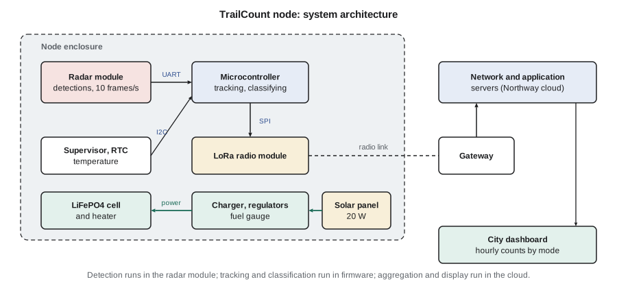
Hardware-software partitioning decides which functions run in dedicated hardware and which in software, and, in a distributed system, which software runs where. CMP-450 made this decision for the NS-5, moving the radar filter from firmware into an FPGA because the processor could not keep up. TrailCount faces the opposite pressure. Its workload is small, a few people per minute at most, but its energy budget is tiny. The guiding question becomes: where can each function be done with the least energy, acceptable cost and acceptable risk?
The radar module already contains a signal processor that turns raw chirps into detections. Doing that work in the team's own microcontroller would require streaming raw samples at megabits per second over a fast bus and running FFTs continuously, which would cost more energy and many months of work. So detection stays in the module. Tracking and classification need only a few dozen detections per frame, which the microcontroller handles in a fraction of a millisecond, and they are the functions the team most needs to tune, so they belong in firmware the team controls. Aggregation for the city, long-term storage and display have no energy constraint at all, so they live in the cloud.
This three-way split has a cost: three places where things can go wrong, and two interfaces to define precisely. Lesson 5 is about those interfaces. It also has a benefit beyond energy. Each element can be developed and tested separately. Amira can develop the tracker on recorded detection files from Jonah's field sessions long before the custom board exists, and Lucas can develop the payload decoder with simulated uplinks.
Architectural views
No single diagram captures an architecture. Systems engineers use several views, each answering a different question. The block diagram above is a physical view: what boxes exist and how they connect. A functional view shows data flowing through processing steps: detections to tracks to classified passages to bins to uplinks. A software view shows firmware modules and their dependencies: drivers, the tracker, the classifier, the counter, the power manager and the radio stack. A deployment view shows where each piece runs: in the module, the microcontroller, the gateway or the cloud. A behavioural view, usually a state machine, shows operating modes.
The TrailCount firmware has five modes. In normal mode the radar runs at 10 frames per second and the firmware tracks every target. In night mode, from 23:00 to 05:00 when traffic is nearly zero, the radar runs at half duty. In low-battery mode, below 20 % state of charge, the node stops the heater and keeps only counting and minimal reporting. In service mode, entered with a magnet near a reed switch, a technician can read status over a short-range link. And in a fault mode, entered after repeated watchdog resets, the node sends a fault report and retries at increasing intervals. Writing the mode diagram early forced the team to decide what happens in awkward cases, such as a cold battery that cannot be charged while the panel is producing power.
Choosing the main components
Architecture and component selection proceed together, because the parts available constrain what the architecture can be. The team selected components with a short trade study for each and recorded the results. A few principles guided them.
- Prefer parts with long production life, multiple distributors and stock. A part with a 40-week lead time can sink a project with a 26-week schedule.
- Prefer pre-certified radio modules. A module with its own regulatory approval saves months of testing, as lesson 11 explains.
- Choose a microcontroller family with good low-power modes, mature tools and a debugger the team already owns, with headroom of at least two times in flash, RAM and processing for features nobody has thought of yet.
- Check temperature ratings against SYS-03. Many inexpensive parts are rated only from 0 °C or −20 °C. The team rejected a cheap real-time clock and a popular supercapacitor because neither was rated to −30 °C.
- Check the radar module's detection limits: minimum speed, maximum number of targets per frame and field of view against the trail's geometry.
The power budget
For an off-grid node, the power budget is the most important architectural calculation. It allocates SYS-04 (five days without sun) and the winter energy balance into requirements on every element. Keisha built it as a script so that the team could update it every time a datasheet or a measurement changed a number.
# Power budget, solar balance and battery autonomy for the TrailCount node
loads = {  # name: (active power mW, duty cycle)
    'Radar module (frames)':   (750, 0.30),
    'Microcontroller':         (36,  0.35),   # sleeps between radar frames
    'LoRa radio transmit':     (420, 0.37 / 900),  # 0.37 s every 15 min
    'LoRa radio receive slots':(40,  2.0 / 900),
    'Sensors and supervisor':  (4,   1.00),
}
eff = 0.85                                     # regulator efficiency
avg = sum(p * d for p, d in loads.values()) / eff
for n, (p, d) in loads.items():
    print(f"{n:26s} {p:5.0f} mW x {d:7.4f} = {p * d:6.1f} mW")
print(f"Average from battery (after {eff:.0%} regulator): {avg:.0f} mW = {avg * 24 / 1000:.2f} Wh/day")

# night mode: radar duty drops to 0.15 between 23:00 and 05:00 (6 h)
night = (750 * 0.15 + 36 * 0.20 + 4 + 0.18 + 0.09) / eff
day_avg = (avg * 18 + night * 6) / 24
daily = day_avg * 24 / 1000
print(f"With night mode: {day_avg:.0f} mW average = {daily:.2f} Wh/day")

battery_wh = 12 * 3.2          # 12 Ah LiFePO4 at 3.2 V nominal
usable = battery_wh * 0.80     # keep 20 % in reserve
print(f"Autonomy with no sun: {usable / daily:.1f} days (requirement: 5)")

# winter solar balance: panel watts x sun-hours x derating
for panel in (10, 20):
    for site, sun_h in (('December, worst month', 1.3), ('June', 5.0)):
        harvest = panel * sun_h * 0.70
print(f"{panel} W panel, {site:22s}: {harvest:5.1f} Wh/day, balance {harvest - daily:+5.1f} Wh/day")Radar module (frames) 750 mW x 0.3000 = 225.0 mW Microcontroller 36 mW x 0.3500 = 12.6 mW LoRa radio transmit 420 mW x 0.0004 = 0.2 mW LoRa radio receive slots 40 mW x 0.0022 = 0.1 mW Sensors and supervisor 4 mW x 1.0000 = 4.0 mW Average from battery (after 85% regulator): 285 mW = 6.83 Wh/day With night mode: 250 mW average = 6.00 Wh/day Autonomy with no sun: 5.1 days (requirement: 5) 10 W panel, December, worst month : 9.1 Wh/day, balance +3.1 Wh/day 10 W panel, June : 35.0 Wh/day, balance +29.0 Wh/day 20 W panel, December, worst month : 18.2 Wh/day, balance +12.2 Wh/day 20 W panel, June : 70.0 Wh/day, balance +64.0 Wh/day
The radar dominates. At 750 mW while active and 30 % duty, it contributes 225 mW of the 285 mW average drawn from the battery after regulator losses. The radio, which students often worry about first, contributes almost nothing, because it transmits for 0.37 s every 15 minutes. That single observation shaped the firmware priorities: every percentage point of radar duty matters far more than radio settings.
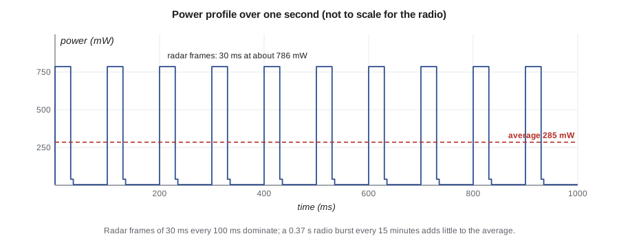
With night mode, the daily energy falls to 6.00 Wh. The 12 Ah LiFePO4 cell holds 38.4 Wh at its nominal 3.2 V; keeping a 20 % reserve leaves 30.7 Wh, which is 5.1 days of autonomy. That just meets SYS-04, with almost no margin, so the team recorded it as a risk and decided to keep the night-mode feature mandatory.
The solar balance shows why the panel grew from 10 W to 20 W. In the worst winter month, the site receives only about 1.3 equivalent full-sun hours per day on a steeply tilted panel, a figure the team read from a solar resource map and treated as approximate. With a 0.70 derating for panel temperature, dirt, charger losses and imperfect orientation, a 10 W panel harvests about 9.1 Wh/day, only 3.1 Wh/day more than the load. After a five-day snowstorm leaves a deficit of about 30 Wh, that surplus would need ten clear days to refill the battery. A 20 W panel has a surplus of 12.2 Wh/day and recovers in under three days. The extra panel cost was small compared with a winter data gap.
Worked problem
Sizing the battery for a longer autonomy target
The city asks whether the node could run 7 days without sun. With 6.00 Wh/day and a 20 % reserve, what battery capacity in ampere-hours at 3.2 V is needed?
Show solution
- Energy required over 7 days:
- \[E = 7 \times 6.00 = 42.0\ \text{Wh}\]
- Only 80 % of the battery may be used, so the nominal energy must be
- \[E_{\text{bat}} = \frac{42.0}{0.80} = 52.5\ \text{Wh}\]
- Convert to capacity at the nominal voltage:
- \[C = \frac{52.5\ \text{Wh}}{3.2\ \text{V}} \approx 16.4\ \text{Ah}\]
- Cold reduces usable capacity further, so a real design would check the cell's low-temperature data before choosing.
Answer: About 16.4 Ah, before any allowance for reduced capacity in the cold.
Cold batteries: an architectural decision
Lithium iron phosphate cells were chosen for their safety, cycle life and tolerance of full charge, but they share a limitation with other lithium chemistries: charging below about 0 °C can plate lithium on the anode, permanently reducing capacity and creating a safety hazard. Cell datasheets set the exact limits. In a Canadian or Michigan winter the cell may sit below freezing for weeks, while the panel produces power on sunny days.
This is not a detail to leave to the detailed design, because the possible responses change the architecture. The team considered three. A charger that simply refuses to charge below 0 °C is simple but wastes winter sun. A cell with a small heater, powered from the panel when the sun is shining, warms the cell to a safe temperature before charging. An insulated battery compartment slows temperature swings and reduces heater energy. The team chose a charger with temperature cutoffs plus a heater controlled by the firmware and powered only from surplus panel energy, inside an insulated compartment. The decision added an interface (the heater control line) and a firmware mode, and it became the highest-ranked item in the failure modes analysis in lesson 6.
Architecture principles and the architecture document
Alongside the diagrams, the team wrote down a few principles that guide detailed decisions: keep the radar module replaceable through a defined interface, so a better module can be adopted later; never lose counts, so bins are stored before transmission and deleted only after confirmation; fail safe and quiet, so a fault produces a report and a recovery attempt but never a stream of transmissions; and make every field unit identifiable, with firmware version and hardware revision in every uplink.
The architecture document collects the allocation table, the views, the component selections with rationale, the power budget, the principles and the derived requirements for each subsystem. For TrailCount it was twelve pages long. It was the central document at the preliminary design review in week 10, where Professor Osei, Ines and a second faculty reviewer examined whether the architecture could meet the requirements before the team committed money to custom hardware.
Common mistakes
MistakeStarting the circuit board before the architecture is agreed.
InsteadAgree the allocation, interfaces and power budget at a preliminary design review before committing to custom hardware.
MistakeWorrying about the radio's power while ignoring the sensor's.
InsteadBuild a power budget with active power and duty for every load; optimize the largest contributor first.
MistakeAssuming batteries can be charged whenever the sun shines.
InsteadCheck the charge temperature limits of the chemistry and design heating, insulation or charge inhibition into the architecture.
MistakeChoosing parts rated only for commercial temperature ranges.
InsteadCheck every part's rating against the environmental requirements, including passive parts and displays.
MistakeDrawing one block diagram and calling it the architecture.
InsteadUse several views, including functional, software, deployment and behavioural views, plus written principles.
Summary and key terms
- An architecture defines the elements, their responsibilities, their interfaces and the principles that guide detailed design.
- An allocation table assigns each function to an element and exposes gaps and overlaps.
- Partitioning places each function where it costs the least energy, effort and risk; for TrailCount that is the radar module, the firmware or the cloud.
- Several views (physical, functional, software, deployment, behavioural) together describe the architecture.
- The power budget allocates autonomy and winter balance to every load; the radar duty dominates, and night mode is mandatory.
- Battery charge temperature limits are an architectural concern that adds a heater, insulation and a firmware mode.
- System architecture
- The fundamental organization of a system: its elements, their relationships and the principles governing its design.
- Allocation
- Assigning a function or requirement to a specific element of the architecture.
- Hardware-software partitioning
- Deciding which functions run in dedicated hardware and which in software, and where.
- Architectural view
- A representation of the architecture from one perspective, such as physical, functional or behavioural.
- Operating mode
- A distinct state of system behaviour, such as normal, night, low-battery or service mode.
- Power budget
- A table of each load's active power and duty cycle that yields average power and energy per day.
- Duty cycle
- The fraction of time a load is active.
- Autonomy
- How long a system can run from stored energy without any input.
Practice problems
Work each problem on paper first, then reveal the answer to check.
A load draws 120 mW for 50 ms every second. What is its average power?
Show answer
120 mW × 0.05 = 6 mW.
The TrailCount radar duty drops from 30 % to 25 %. How much does the average battery power fall, with an 85 % regulator?
Show answer
750 × 0.05 = 37.5 mW at the load; 37.5 / 0.85 ≈ 44 mW from the battery.
A 20 W panel sees 1.3 sun-hours with a 0.70 derating. What does it harvest per day?
Show answer
20 × 1.3 × 0.70 = 18.2 Wh/day.
Why is classification done in firmware rather than in the cloud for TrailCount?
Show answer
Sending every detection would far exceed the LoRaWAN capacity and energy budget; only aggregated counts can be sent.
Lesson quiz · 5 questions
Score 60% or more to complete this lesson.
Create a free account to save your progress, take quizzes and earn a certificate.