
BLR-220 · Lesson 8 of 12 · 19 min
Tubes, tube sheets and tube expanding
Ironbridge's exchanger shop is a separate bay at the end of the Nisku fabrication shop, with a bundle cradle, a tube puller, a wash pad and racks of tube stock. Desmond Pryce runs it. He has retubed exchangers for twenty-five years and has strong opinions about tube expanding, most of which, Kiera learns, come from joints he has seen leak. In late September, before Northgate's turnaround sends him the E-1105 bundle, he gives Kiera two days on a practice tube sheet: a thick plate drilled in a pattern, with stubs of tube to cut, pull, clean, insert and roll. "Rolling a tube takes ten seconds," he says. "Getting it right takes knowing what's happening to the metal."
Tubes are the heart of boilers and heat exchangers, and the joint between a tube and its tube sheet is the place where most leaks happen. This lesson covers tube materials and sizes, tube sheets and their layouts, and the expanded joint that holds them together.
Tubes
Heat exchanger and boiler tubes are made to tube specifications, not pipe specifications, and are sized by their outside diameter and wall thickness. A 19.05 mm (3/4 in) tube is exactly that outside diameter. Wall thickness is given in millimetres, inches or, in North American exchanger practice, by the Birmingham Wire Gauge (BWG), in which a larger number means a thinner wall: 14 BWG is 2.11 mm (0.083 in), 16 BWG is 1.65 mm (0.065 in). Tubes are bought to a minimum wall or an average wall; a minimum wall tube is never thinner than the stated wall, while an average wall tube may be thinner by a tolerance.
| Material | Typical specification | Where it is used |
|---|---|---|
| Carbon steel, cold drawn seamless | SA-179 | Exchangers and condensers in non-corrosive service |
| Carbon steel, welded | SA-214 | Exchangers where welded tube is accepted |
| Carbon steel, boiler tube | SA-210, SA-192 | Boiler waterwalls, boiler banks, economizers |
| Chromium-molybdenum alloy | SA-213 T11, T22, T91 | Superheaters and high-temperature exchangers |
| Stainless steel | SA-213 or SA-249 grades 304 and 316 | Corrosive or clean services |
| Copper alloys | Admiralty, copper-nickel | Cooling water exchangers and condensers |
| Titanium | SB-338 | Seawater and aggressive cooling water |
Tubes are straight or U-bent. A U-tube bundle has no rear tube sheet; each tube bends back on itself, so the bundle can grow freely, but the inside of the bends cannot be cleaned mechanically. U-tubes are bent to a set of radii, with the tightest bends in the inner rows, and the bends are thinned on the outside and thickened on the inside by bending.
Tube sheets and layouts
A tube sheet is a thick plate drilled with holes for the tubes. In an exchanger, it separates the shell side fluid from the tube side fluid, so every hole is a potential leak path between them. Tube sheets are often forged, sometimes clad with a corrosion-resistant layer on one face, and grooved on the tube side face for the pass partition plates in the channel. Their thickness is set by design rules that consider pressure on both sides and the bending of the sheet; a typical refinery exchanger tube sheet is 40 to 100 mm (1 1/2 to 4 in) thick.
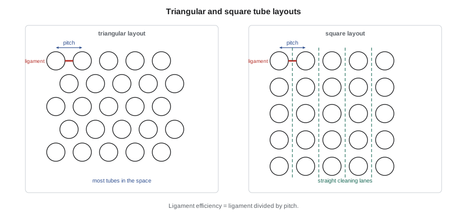
The tubes are arranged in a layout described by the pitch, the distance between the centres of neighbouring holes, and the pattern. A triangular layout, with tubes at the corners of equilateral triangles, packs the most tubes into a given shell. A square layout leaves straight lanes between the rows so the outside of the tubes can be cleaned with a water lance or brush, which matters when the shell side fluid fouls. Rotated square and rotated triangular layouts set the pattern at 45 or 30 degrees to the flow. The pitch is usually at least 1.25 times the tube outside diameter, which leaves enough metal between holes for the sheet's strength and for the expanding process.
The strip of metal between two neighbouring holes is the ligament. The ligament efficiency is the ligament divided by the pitch, the fraction of the sheet's width that is left as metal along a row of holes. It is what limits how close tubes can be, and it is also why boiler drums are thicker where their tube holes are. Ligaments can be damaged by over-rolling, which stretches the holes and thins the ligament, and by cracking from thermal stress. The code below counts how many holes fit inside E-1105's outer tube limit in each layout, works out the ligament and gives the rolled inside diameters for three amounts of wall reduction.
# E-1105 tube sheet: hole count by layout, ligament, and the roll-in target (metric)
import math

od = 19.05            # tube outside diameter, mm
pitch = 25.4      # hole spacing (pitch), mm
otl = 800          # outer tube limit diameter, mm
lane = 16        # pass partition lane width (clear), mm

def count(layout):
    n = 0
    dy = pitch * math.sqrt(3) / 2 if layout == "triangular" else pitch
    rows = int(otl / dy) + 2
    for j in range(-rows, rows + 1):
        y = (j + 0.5) * dy
        shift = pitch / 2 if (layout == "triangular" and j % 2) else 0
        for i in range(-rows, rows + 1):
            x = i * pitch + shift
            if math.hypot(x, y) + od / 2 > otl / 2:
                continue                      # outside the outer tube limit
            if abs(y) < (lane + od) / 2:
                continue                      # would sit in the pass partition lane
            n += 1
    return n

for lay in ("triangular", "square"):
    print(f"{lay:10} pitch {pitch} mm: {count(lay)} holes")

hole = 19.30        # standard fit tube hole diameter, mm
lig = (pitch - hole) / pitch
print(f"Ligament between holes: {pitch - hole:.2f} mm, efficiency {lig:.0%}")

# Roll-in target: wall reduction for carbon steel tubes
wall = 2.11
id0 = od - 2 * wall
clear = hole - od
for wr in (0.05, 0.07, 0.08):
    idf = id0 + clear + 2 * wall * wr
print(f"wall reduction {wr:.0%}: rolled inside diameter {idf:.2f} mm")triangular pitch 25.4 mm: 793 holes square pitch 25.4 mm: 680 holes Ligament between holes: 6.10 mm, efficiency 24% wall reduction 5%: rolled inside diameter 15.29 mm wall reduction 7%: rolled inside diameter 15.38 mm wall reduction 8%: rolled inside diameter 15.42 mm
The triangular layout fits 793 holes inside E-1105's outer tube limit with a two-pass partition lane, about 17 percent more than the square layout. That is the bundle's actual tube count. The ligament is about 6.1 mm (0.24 in), a little under a quarter of the pitch, which is normal.
The expanded joint
The most common way to join a tube to a tube sheet is expanding: the tube end, inside its hole, is stretched outward until it presses hard against the hole wall. In roller expanding, a tool called a roller expander is pushed into the tube end. It has a tapered mandrel in the middle and three or more hardened rolls held in a cage around it. As the mandrel is driven in and turned, the rolls press outward and roll around inside the tube, thinning the tube wall and pushing the metal out against the hole. The tube metal is stretched beyond its yield point, so it stays expanded, while the tube sheet, which is stretched less, springs back elastically and grips the tube. That residual grip is what makes the joint tight and strong.
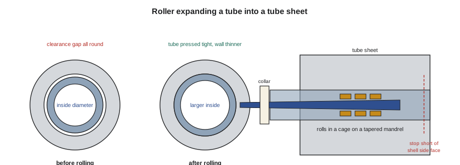
How much to expand is measured by wall reduction, the percentage by which the tube wall is thinned after the tube has first been expanded enough to fill the clearance in the hole. It is worked out from the tube's inside diameter before and after rolling and the hole and tube diameters:
Here d_f is the inside diameter after rolling, d_i the inside diameter before, D_h the hole diameter, D_o the tube outside diameter and t the tube wall. The first part of the top line is how much the inside diameter grew; the second part is how much of that growth only closed the clearance. What is left, divided by twice the wall, is the fraction by which the wall was thinned. Recommended ranges depend on the material: for carbon steel and low-alloy tubes, TEMA's guidance is roughly 5 to 8 percent, and API Standard 660 sets a maximum of 8 percent; for stainless steel and harder materials, less, and for copper alloys, more. The aim is the lowest reduction that gives a tight joint. Under-rolled tubes leak; over-rolled tubes are thinned too much, work-harden, and stretch the holes and ligaments so that neighbouring joints loosen.
| Rolling practice | Why |
|---|---|
| Measure each hole and the tube's inside diameter before rolling | Holes and tubes vary; the target rolled diameter depends on both |
| Set the expander's torque or depth to give the target wall reduction, then check by measurement | Torque settings are a starting point; the micrometer is the proof |
| Stop the rolled length about 3 mm (1/8 in) short of the shell side face | Rolling past the face bulges the tube and cuts it at the face |
| Roll in steps on thick tube sheets, overlapping each step | Long single rolls can lengthen tubes and push them out of the far sheet |
| Clean the tube end and hole to bright, dry metal | Dirt, oil and scale stop the tube gripping and leave leak paths |
| Re-roll leaks lightly, never more than once or twice | Repeated rolling thins and hardens the tube |
Welded joints and plugging
Expanded joints are sometimes not enough. In high-pressure, high-temperature or lethal services, tubes are welded to the tube sheet as well as expanded. A seal weld closes the leak path but is not counted on for strength; a strength weld carries the tube load. Welded joints need a qualified procedure and welder, like any pressure weld, and the expansion may be done before or after welding as the procedure states. Hydraulic expanding, which uses water pressure inside the tube end, gives a more uniform joint and is used on thick tube sheets and welded joints.
A leaking or thinned tube in an exchanger that cannot be retubed yet is plugged: a tapered plug is driven or welded into each end of the tube, taking it out of service. Plugging reduces the exchanger's capacity, and plants set limits; when too many tubes are plugged, often around ten percent, the bundle is retubed or replaced. E-1105 has reached that limit, which is why it is coming to Desmond's shop.
Worked problem
Wall reduction from measurements
A 19.05 mm (0.750 in) tube with a wall of 2.11 mm (0.083 in) sits in a 19.30 mm (0.760 in) hole. Its inside diameter is 14.83 mm (0.584 in) before rolling and 15.37 mm (0.605 in) after. What is the wall reduction?
Show solution
- Growth of the inside diameter: 15.37 − 14.83 = 0.54 mm.
- Clearance: 19.30 − 19.05 = 0.25 mm.
- Thinning of two walls: 0.54 − 0.25 = 0.29 mm.
- Wall reduction: 0.29 ÷ (2 × 2.11) = 6.9 percent.
Answer: About 6.9 percent, inside the 5 to 8 percent range for carbon steel.
Practising on the training tube sheet
On Desmond's practice tube sheet, Kiera rolls her first twenty tubes and measures each one. Her first five are all over 8 percent, because she holds the expander in the tube for a second after the torque control trips. Desmond has her roll the next five with a stopwatch, then measure again; they come out between 6 and 7 percent. He then shows her two faults she will meet on real bundles. A tube whose end is not cleaned leaves a dull ring of scale in the hole when it is pulled out again, and the joint never seals. A tube rolled past the shell side face shows a bulge just beyond the sheet, where the roll has thinned the tube outside the hole; in service, that bulge is where the tube cracks.
Desmond also shows her the tools the exchanger shop uses to keep rolling consistent: torque-controlled air and electric drives that stop at a set torque, expanders matched to the tube's inside diameter and the tube sheet thickness, and a set of internal micrometers and dial bore gauges checked against a ring gauge each morning.
Common mistakes
MistakeRolling to a torque setting without measuring.
InsteadMeasure the rolled inside diameter and work out the wall reduction.
MistakeRolling through the shell side face of the tube sheet.
InsteadStop about 3 mm short so the tube is not bulged and cut at the face.
MistakeRolling a leaking tube again and again.
InsteadRe-roll lightly once or twice; beyond that, plug it or replace it.
MistakeLeaving oil from the expander on the tube and hole.
InsteadClean and dry the joint surfaces; lubricate only the tool as the maker says.
Summary and key terms
- Tubes are sized by outside diameter and wall, often by BWG, and bought to minimum or average wall.
- Triangular layouts fit more tubes; square layouts allow cleaning of the shell side.
- The ligament between holes limits the pitch and is damaged by over-rolling.
- Roller expanding thins the tube wall so the tube grips the elastically recovering tube sheet.
- Wall reduction is measured from inside diameters before and after rolling; carbon steel is commonly 5 to 8 percent.
- Welded joints add seal or strength welds; leaking tubes are plugged until the bundle is retubed.
- BWG
- Birmingham Wire Gauge: a tube wall thickness scale in which larger numbers are thinner.
- Pitch
- The distance between the centres of neighbouring tube holes.
- Ligament
- The metal between two neighbouring holes.
- Roller expander
- A tool with a tapered mandrel and rolls that expands a tube into its hole.
- Wall reduction
- The percentage thinning of the tube wall after the hole clearance is closed.
- Tube plug
- A tapered plug that takes a tube out of service.
Practice problems
Work each problem on paper first, then reveal the answer to check.
Why does a square layout make cleaning easier?
Show answer
It leaves straight lanes between the rows so a lance or brush can reach the outside of every tube.
What gives an expanded joint its grip?
Show answer
The tube is stretched past its yield point while the tube sheet springs back elastically and squeezes it.
A tube's inside diameter grows 0.50 mm during rolling. The clearance was 0.25 mm and the wall is 2.11 mm. What is the wall reduction?
Show answer
(0.50 − 0.25) ÷ 4.22 = 5.9 percent.
Why stop rolling short of the shell side face?
Show answer
Rolling past the face bulges the tube outside the hole and can cut it at the face.
Lesson quiz · 5 questions
Score 60% or more to complete this lesson.
Create a free account to save your progress, take quizzes and earn a certificate.