
BLR-220 · Lesson 11 of 12 · 19 min
Pressure testing and leak testing
In late July, V-412 is finished. Every nozzle is in, every weld has been examined, the internal clips are welded and the vessel is ready for its hydrostatic test. Harjit Gill writes the test procedure, and Kiera helps set up the test in the fabrication shop's test bay: blinds and test gaskets on every nozzle, a vent at the top, a drain at the bottom, a test pump, a relief valve and two pressure gauges. Grant Mahler, the ABSA safety codes officer, will witness the test and inspect the vessel at pressure. Before they begin, Harjit walks Kiera around the setup and asks her to point out everything that could hurt someone if it failed.
Pressure testing is the last step in building or repairing a pressure part, and the proof that it is strong and tight. It is also one of the most hazardous tasks boilermakers perform, because a test puts the equipment above its working pressure on purpose. This lesson covers hydrostatic and pneumatic tests, the rules for test pressure and gauges, and the leak tests used on reinforcing pads, tube joints and sensitive equipment.
Why equipment is tested
A pressure test does two jobs. As a strength test, it loads the equipment above its working pressure to show that it has no gross defects and that it will carry its design load with a margin. As a leak test, it shows that the welds, joints and gaskets are tight. A test also relieves some of the peak stresses left by fabrication, because the most highly stressed points yield slightly and settle. New boilers and vessels are tested when they are built, and repaired or altered ones are tested as the repair code and the inspector require.
Water is the normal test medium, because it barely compresses. If a vessel full of water at test pressure fails, the pressure falls almost instantly as the water escapes, and little energy is released. A gas, by contrast, stores energy as it is compressed, and a failure during a pneumatic test can release it as an explosion. That single difference is the reason hydrostatic testing is preferred whenever the equipment can take the weight of water and be dried afterwards.
Test pressures
The test pressure is set by the construction code. For a vessel built to ASME Section VIII, Division 1, the standard hydrostatic test is at least 1.3 times the maximum allowable working pressure, multiplied by the ratio of the material's allowable stress at the test temperature to its allowable stress at the design temperature. The ratio makes up for the fact that metal is stronger cold than hot: a vessel designed for high temperature is tested at a higher pressure at room temperature so that it is loaded to the same proportion of its strength. For a power boiler built to Section I, the hydrostatic test is at 1.5 times the maximum allowable working pressure, with limits on how far above that the pressure may go. A pneumatic test under Section VIII, Division 1, when one is permitted, is at 1.1 times the MAWP times the same stress ratio. Repairs and alterations are tested under the NBIC or the provincial rules at a pressure the inspector accepts, which is often lower than the original test.
| Equipment and code | Test | Usual test pressure |
|---|---|---|
| Pressure vessel, ASME VIII Div. 1 | Hydrostatic | 1.3 × MAWP × stress ratio |
| Pressure vessel, ASME VIII Div. 1 | Pneumatic (where permitted) | 1.1 × MAWP × stress ratio |
| Power boiler, ASME Section I | Hydrostatic | 1.5 × MAWP |
| Repairs and alterations | Hydrostatic or alternative | As the repair code and inspector require |
The test pressure is measured at the top of the vessel. The water's weight adds pressure lower down, so the bottom of a tall vessel sees more than the gauge at the top shows. Designers check that the bottom of a vessel tested in the vertical position is not overstressed, and a vessel designed to be tested horizontally in the shop may need a lower top pressure if it is tested standing up in the field.
# V-412: hydrostatic test pressure, gauge choice, and why a pneumatic test is treated differently (metric)
import math
mawp = 1_700                  # kPa gauge, at the top of the vessel
s_test, s_design = 138, 138  # allowable stress at test and design temperature
hydro = 1.3 * mawp * (s_test / s_design)
print(f"Hydrostatic test pressure: {hydro:,.0f} kPa at the top")
head = 8.2                  # liquid height from the top gauge to the bottom, m
static = head * 9.81
print(f"Water head adds {static:,.0f} kPa at the bottom: {hydro + static:,.0f} kPa there")
print(f"Close inspection at no more than test / 1.3 = {hydro / 1.3:,.0f} kPa")

for rng in [2_500, 4_000, 10_000]:
    ok = 1.5 * hydro <= rng <= 4 * hydro
    print(f"gauge 0-{rng:,} kPa: {rng / hydro:.1f} x test -> {'usable' if ok else 'not usable'}")

# Stored energy in compressed gas at a pneumatic test (common estimate for an ideal gas, k = 1.4)
vol = math.pi / 4 * 1.8 ** 2 * 7.32 + 2 * math.pi * 1.8 ** 3 / 24   # shell + two 2:1 heads, m3
pneu = 1.1 * mawp
p_abs = pneu + 101.3
energy = 2.5 * p_abs * 1000 * vol  * (1 - (101.3 / p_abs) ** 0.2857)   # joules
print(f"Vessel volume {vol:,.1f} m3; pneumatic test {pneu:,.0f} kPa")
print(f"Stored energy {energy / 1e6:,.1f} MJ, about {energy / 4.5e6 :,.0f} kg of TNT equivalent")
print(f"The same vessel full of water at {hydro:,.0f} kPa stores a small fraction of that, because water barely compresses")Hydrostatic test pressure: 2,210 kPa at the top Water head adds 80 kPa at the bottom: 2,290 kPa there Close inspection at no more than test / 1.3 = 1,700 kPa gauge 0-2,500 kPa: 1.1 x test -> not usable gauge 0-4,000 kPa: 1.8 x test -> usable gauge 0-10,000 kPa: 4.5 x test -> not usable Vessel volume 20.2 m3; pneumatic test 1,870 kPa Stored energy 56.8 MJ, about 13 kg of TNT equivalent The same vessel full of water at 2,210 kPa stores a small fraction of that, because water barely compresses
For V-412, the stress ratio is 1.0, because its steel has the same allowable stress at its design temperature as at room temperature, so the test pressure is 2,210 kPa (325 psi). Harjit sets the relief valve to protect the vessel from going far above that and chooses the 0 to 4,000 kPa (0 to 600 psi) gauges, which read the test pressure near the middle of their range. The code is the reason for the choice: the range of the indicating gauge should be about twice the intended maximum test pressure, and never less than 1.5 times or more than 4 times it, so that the gauge is neither near its limit nor too coarse to read accurately. Two gauges are used, one where the pump operator can see it and one at the top of the vessel, and both have current calibration stickers.
Running a hydrostatic test
- Prepare. All welding and heat treatment are finished. Test blinds and gaskets are rated for the test pressure. Supports are checked for the weight of water, which for V-412 is about 20 tonnes more than the empty vessel. Spring hangers on connected piping are pinned.
- Fill and vent. Fill from the bottom with clean water while venting at the highest point until water runs out with no air. Trapped air turns a hydrostatic test into a partly pneumatic one.
- Check the water and metal temperature. The metal must be warm enough to avoid brittle fracture; Section VIII recommends the metal be at least 17 °C (30 °F) above its minimum design metal temperature. Water should also not be so hot that it scalds anyone. For stainless steel, the water's chloride content is limited, often to about 50 ppm, to avoid stress corrosion cracking.
- Pressurize in steps. Raise the pressure slowly, stopping at intervals to check for leaks and movement, to the test pressure, and hold it for the time the procedure requires.
- Inspect. Reduce the pressure to the inspection pressure, not more than the test pressure divided by 1.3 for a Section VIII vessel, before anyone goes close. The inspector then examines all welds and joints.
- Depressurize and drain. Release the pressure slowly, open the top vent before draining so the vessel cannot be pulled into a vacuum, drain completely and dry the vessel if its service requires.
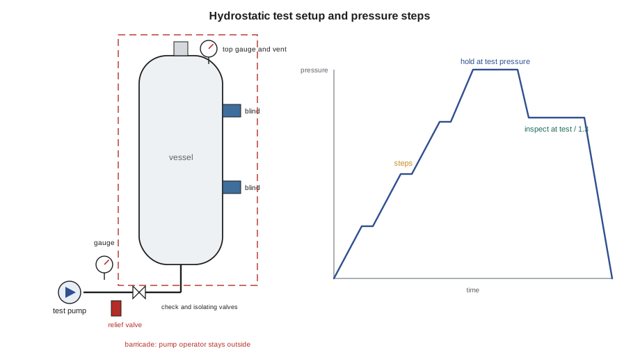
The danger zones of a test are the blinds, the test gaskets, the temporary connections and the hoses, and the line of fire of anything that could blow out. People stay out of the barricade while the pressure is above the inspection pressure. Nobody tightens a leaking bolt or tries to stop a leak while the system is pressurized; the pressure comes off first. At V-412's test, Kiera stands outside the barricade with Harjit through the hold, then walks the vessel with Grant at the inspection pressure. The welds are dry, the blinds hold, and the test is recorded and signed.
Pneumatic testing
Some equipment cannot be filled with water: the supports or foundations will not carry the weight, the internals or linings would be damaged, or traces of water cannot be tolerated in service. These items may be tested pneumatically, with air or nitrogen, where the code allows it. The code that runs alongside the hydrostatic calculation above shows why such a test is treated so seriously: the same vessel at its pneumatic test pressure stores tens of megajoules in compressed gas, energy that would be released in a burst. Pneumatic tests are therefore done under extra controls: a written procedure approved by the engineer and inspector, a calculated exclusion zone around the equipment, examination of welds before the test, pressure raised slowly to half the test pressure and then in small steps, and inspection only at a reduced pressure. Many companies require a separate approval from a senior engineer for every pneumatic test.
Leak tests
A leak test finds leaks that a strength test may not reveal, and some joints can only be checked by a dedicated leak test.
| Test | How it works | Used for |
|---|---|---|
| Pad telltale test | Low-pressure air through the pad's telltale hole, soap solution on the pad welds | Reinforcing pads, before the vessel's hydrostatic test |
| Bubble test | Soap solution or a vacuum box over a joint under a pressure difference | Tank bottoms, welds, small joints |
| Shell side test of an exchanger | Shell filled and pressurized with the channel and heads off | Finding leaking tubes and tube-to-tube sheet joints |
| Test ring on a floating head exchanger | A ring that seals the shell to the floating tube sheet so its tube ends are visible | Testing the joints at the floating end |
| Helium or tracer gas test | Tracer gas inside, a detector outside | Very tight joints, cryogenic and toxic services |
Reinforcing pads are tested before the hydrostatic test, because once the vessel is full of water, a leak in a pad weld cannot be seen. At V-412, the pad on nozzle N2 is tested with air at a low pressure through its telltale hole while Kiera brushes soap solution on the pad's welds; no bubbles appear. For exchangers, the shell side test with the channel and heads removed lets the crew see every tube end at the stationary tube sheet. On a floating head exchanger, a test ring bolted in place of the shell cover seals the shell to the floating tube sheet so that its tube ends can be seen too. Lesson 12 uses both.
Worked problem
Test pressure and gauge range
A vessel has an MAWP of 1,000 kPa (150 psi) at its design temperature, where its allowable stress is 118 MPa (17,100 psi). At the test temperature, the allowable stress is 138 MPa (20,000 psi). What is the hydrostatic test pressure, and which gauge range, 0 to 1,600 kPa, 0 to 4,000 kPa or 0 to 10,000 kPa, can be used?
Show solution
- Stress ratio: 138 ÷ 118 = 1.169.
- Test pressure: 1.3 × 1,000 × 1.169 = 1,520 kPa.
- Gauge range must be between 1.5 and 4 times: 2,280 to 6,080 kPa.
- Only the 0 to 4,000 kPa gauge is within the limits.
Answer: Test at about 1,520 kPa with the 0 to 4,000 kPa gauge.
Common mistakes
MistakeLeaving air trapped at the top of a vessel during a hydrostatic test.
InsteadVent at the highest point until solid water runs out.
MistakeStanding beside a blind or test gasket at full test pressure.
InsteadStay outside the barricade until the pressure is down to the inspection pressure.
MistakeTightening bolts on a leaking flange under pressure.
InsteadRelease the pressure first, then fix the leak and retest.
MistakeDraining a vessel with all its vents closed.
InsteadOpen the top vent first so the vessel cannot collapse under vacuum.
MistakeUsing a gauge whose range is ten times the test pressure.
InsteadUse a gauge with a range about twice the test pressure, within 1.5 to 4 times.
Summary and key terms
- A pressure test proves strength and tightness; water is used because it stores little energy.
- Section VIII vessels are tested at 1.3 × MAWP × stress ratio hydrostatically and 1.1 × MAWP × stress ratio pneumatically; Section I boilers at 1.5 × MAWP.
- Gauge range should be about twice the test pressure, never less than 1.5 or more than 4 times it.
- Fill and vent, check temperatures, raise pressure in steps, inspect at reduced pressure, and vent before draining.
- Pneumatic tests store large energies and need extra approvals, exclusion zones and controls.
- Leak tests include pad telltale tests, bubble tests, exchanger shell side and test ring tests, and tracer gas tests.
- Hydrostatic test
- A pressure test with water, usually above the working pressure.
- Pneumatic test
- A pressure test with air or an inert gas, used only when water cannot be.
- Stress ratio
- The allowable stress at test temperature divided by that at design temperature.
- Inspection pressure
- The reduced pressure at which welds are examined closely during a test.
- Test ring
- A fixture that seals a floating head exchanger shell so the floating tube sheet joints can be seen.
- Exclusion zone
- An area kept clear of people during a test because of the stored energy.
Practice problems
Work each problem on paper first, then reveal the answer to check.
Why is water preferred to air for pressure tests?
Show answer
Water barely compresses, so it stores little energy; a failure with water releases far less energy than with gas.
A Section VIII vessel has an MAWP of 2,000 kPa and a stress ratio of 1.0. What is the hydrostatic test pressure and the inspection pressure?
Show answer
Test: 2,600 kPa. Inspection: not more than 2,000 kPa.
Why are reinforcing pad welds tested before the hydrostatic test?
Show answer
Once the vessel is full of water, leaks in the pad welds cannot be seen.
What should be opened before a tested vessel is drained?
Show answer
The top vent, so the vessel is not pulled into a vacuum.
Lesson quiz · 5 questions
Score 60% or more to complete this lesson.
Create a free account to save your progress, take quizzes and earn a certificate.