
BLR-220 · Lesson 4 of 12 · 20 min
Recovery boilers, HRSGs and waste heat boilers
In July, Northgate's cogeneration plant shuts down one of its two trains for a week. Each train is a gas turbine driving a generator, with a heat recovery steam generator, or HRSG, on the turbine exhaust that makes steam for the upgrader. Ironbridge has the inspection support contract: opening access doors, building scaffolds inside the HRSG with the scaffold crew, cleaning areas for inspection and repairing whatever the inspectors find. Kiera spends the week inside the HRSG's casing, between tube rows a little wider than her shoulders. In August, she goes with Dale for two days to the Tamarack Pulp mill, where Ironbridge replaced recovery boiler floor tubes in the spring, to help with a follow-up inspection.
Not every boiler burns fuel to make steam for its own sake. Recovery boilers, HRSGs and waste heat boilers all make steam from heat or fuel that a process has already produced. They are built from the same parts as other water-tube boilers, but each has its own hazards and failure patterns.
The heat recovery steam generator
A gas turbine burns fuel and exhausts gas at about 560 °C (1,040 °F). Without heat recovery, that heat would go up the stack. An HRSG puts tube banks in the exhaust path to turn it into steam. Most HRSGs are horizontal: the gas flows horizontally through a long casing, past vertical tube banks, to a stack at the far end. The tube banks are made as modules called harps, rows of finned tubes welded between an upper and a lower header, which are shipped complete and lifted into the casing.
The gas meets the hottest section first. From the turbine end, a typical single-pressure HRSG has a superheater, then an evaporator connected to a steam drum on top of the casing, then an economizer. Larger HRSGs have two or three pressure levels, each with its own drum, evaporator and economizer, so they can recover heat down to a lower stack temperature. Many have a duct burner, a row of gas burners in the inlet duct, to add heat when the plant needs more steam than the turbine exhaust alone can make.
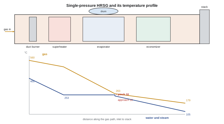
The temperature profile explains how an HRSG is designed. The gas cools steadily from inlet to stack. The water warms in the economizer, then stays at the saturation temperature in the evaporator while it boils, then heats again in the superheater. The narrowest gap between the two lines is usually at the cold end of the evaporator, and it is called the pinch. A smaller pinch means more steam but more tube surface, which costs money and adds back pressure on the turbine. The approach is the gap between the saturation temperature and the water leaving the economizer; it is kept positive so the water does not start to boil in the economizer, where it would cause flow problems and damage.
# Northgate cogeneration HRSG: steam made from gas turbine exhaust, set by the pinch (metric)
gas = 110                  # exhaust flow, kg/s
cp = 1.10                    # exhaust specific heat, kJ/kg K
t_in = 560                 # exhaust entering the HRSG, °C
t_sat = 253               # evaporator saturation temperature, °C
pinch = 10              # gas leaving the evaporator minus t_sat, °C
approach = 10             # t_sat minus water leaving the economizer, °C
h_sh = 3_214                 # superheated steam out, kJ/kg
h_econ_out = 1_052           # water at t_sat - approach, kJ/kg
h_fw = 440                 # feedwater in, kJ/kg

t_gas_pinch = t_sat + pinch
q_high = gas * cp * (t_in - t_gas_pinch)          # superheater + evaporator duty
steam = q_high / (h_sh - h_econ_out)
print(f"Gas leaving the evaporator: {t_gas_pinch:.0f} °C")
print(f"Superheater + evaporator duty: {q_high / 1000:,.1f} MW")
print(f"Steam flow: {steam * 3600:,.0f} kg/h")

q_econ = steam * (h_econ_out - h_fw)
t_stack = t_gas_pinch - q_econ / (gas * cp)
print(f"Economizer duty: {q_econ / 1000:,.1f} MW")
print(f"Stack temperature: {t_stack:.0f} °C")

# What a smaller pinch buys
for p in (5, 10, 15, 20):
    s = gas * cp * (t_in - t_sat - p) / (h_sh - h_econ_out)
print(f"pinch {p:>3} °C -> steam {s * 3600:,.0f} kg/h")Gas leaving the evaporator: 263 °C Superheater + evaporator duty: 35.9 MW Steam flow: 59,840 kg/h Economizer duty: 10.2 MW Stack temperature: 179 °C pinch 5 °C -> steam 60,847 kg/h pinch 10 °C -> steam 59,840 kg/h pinch 15 °C -> steam 58,832 kg/h pinch 20 °C -> steam 57,825 kg/h
The calculation shows how the pinch sets the steam flow. Every 5 °C (9 °F) of pinch is worth roughly 1,000 kg/h (2,200 lb/h) of steam here. Northgate's HRSG was designed with a pinch of about 10 °C (18 °F), and its performance tests compare actual pinch with design to see whether fouling of the fins is reducing heat transfer.
What fails in an HRSG
HRSGs at plants that start and stop often see failures that steady utility boilers rarely do. Every start heats the tubes and headers quickly, and every stop cools them; the thick headers lag behind the thin tubes, so the tube-to-header welds are strained over and over. Over thousands of cycles, this thermal fatigue cracks the welds, usually at the toe on the tube side. In the low-temperature sections, flow-accelerated corrosion thins the tube walls where fast-moving water strips the protective oxide, especially at bends and at tube entries into headers. Condensate left standing in superheater tubes after a shutdown can be blasted into a hot header at the next start, quenching it. And finned tubes collect deposits from the gas, which reduce heat transfer.
At Northgate, the inspectors' plan targets those failure modes. Ironbridge removes insulation from the economizer's lower headers so Annika Sorensen can run ultrasonic thickness readings at the tube bends and phased array checks on a sample of the tube-to-header welds. The crew also opens the inlet duct liner, a set of stainless steel sheets on studs that protect the insulated casing from the hot gas, and finds three liner sheets with broken fasteners, flapping in the gas flow. Loose liner sheets let hot gas reach the casing and make hot spots that show up on the outside as burned paint. Kiera spends a day replacing the fasteners and the sheets with Dale.
| Failure | Where | Cause |
|---|---|---|
| Tube-to-header weld cracking | Superheater and evaporator headers | Thermal fatigue from starts and stops |
| Wall thinning | Economizer and low-pressure evaporator bends | Flow-accelerated corrosion |
| Header quench cracking | Superheater and reheater headers | Condensate thrown into hot headers at start-up |
| Liner and casing hot spots | Inlet duct and casing | Loose or failed liner sheets, insulation damage |
| Fin fouling and corrosion | Cold end | Deposits, acid condensation at low gas temperatures |
The kraft recovery boiler
A kraft pulp mill cooks wood chips in a chemical solution to separate the fibres. The spent solution, called black liquor, contains the cooking chemicals and the dissolved lignin from the wood. A recovery boiler burns the black liquor. The lignin is the fuel; it makes steam and electricity for the mill. The chemicals collect in a molten pool at the bottom of the furnace called the smelt, which flows out through spouts into a dissolving tank, where it is turned back into cooking liquor. A recovery boiler is at the same time the mill's chemical recovery plant and its largest boiler.
The liquor is sprayed into the furnace through guns, dries and burns, and the char falls onto a bed on the furnace floor. The floor and lower walls are in contact with smelt and with a reducing, corrosive atmosphere, so they are built of special tubes, often composite tubes with a stainless steel outer layer bonded to a carbon steel inner tube, and they are studded or coated in some areas to hold a protective layer of frozen smelt. This is the floor that Ironbridge retubed at Tamarack.
The recovery boiler's special danger is the smelt-water reaction. If water from a leaking tube reaches the molten smelt, it can cause a violent explosion. For this reason, recovery boilers are covered by the recommendations of the Black Liquor Recovery Boiler Advisory Committee, BLRBAC, which include an emergency shutdown procedure: when a leak in the pressure parts is suspected, the operators stop firing, drain the boiler quickly to a set level and keep water away from the smelt. Tube welds in the lower furnace are examined thoroughly, and recovery boiler repairs are planned and inspected with more care than almost any other boiler work. When Kiera and Dale visit, the mill's inspector is examining the welds of the floor tubes after the first months of service; Dale shows her the welding procedure, the radiographs and the hydrostatic test record from the spring, all of which the mill keeps for the life of the boiler.
Waste heat boilers in refineries and plants
Many process plants have boilers that cool a hot process gas and make steam at the same time. A sulphur recovery unit in a refinery or gas plant burns hydrogen sulphide to make elemental sulphur, and the hot gas from its burner passes through a fire-tube waste heat boiler. A fluid catalytic cracker's regenerator gas may pass through a CO boiler. Ammonia, hydrogen and other chemical plants have process gas boilers and steam generators. These units are often fire-tube boilers on their sides, with the process gas through the tubes, and many run at temperatures and with gases that attack the tube sheet and the tube inlets. Ceramic ferrules, short ceramic sleeves pushed into the tube inlets, protect the hot tube sheet from the gas. Boilermakers replace ferrules and refractory at every turnaround and retube these boilers when the tubes fail.
| Boiler | Heat source | Watch for |
|---|---|---|
| HRSG | Gas turbine exhaust, often with duct burners | Thermal fatigue, flow-accelerated corrosion, liner failures |
| Kraft recovery boiler | Black liquor fuel; molten smelt in the furnace | Smelt-water reaction; floor and lower wall corrosion |
| Sulphur plant waste heat boiler | Hot gas from the sulphur burner | Tube sheet and ferrule failure, corrosion |
| CO boiler | Flue gas from a catalytic cracker regenerator | Erosion and corrosion from catalyst fines |
| Process gas boiler | Hot reformer or reactor gas | High tube sheet temperatures, hydrogen attack in some services |
Worked problem
Effect of a smaller pinch
An HRSG has exhaust flow of 110 kg/s (873,000 lb/h) with a specific heat of 1.10 kJ/kg K (0.263 Btu/lb °F), entering at 560 °C (1,040 °F). The evaporator boils at 253 °C (488 °F). Superheated steam leaves at 3,214 kJ/kg (1,379 Btu/lb) and water enters the evaporator at 1,052 kJ/kg (452 Btu/lb). How much steam does the HRSG make with a pinch of 15 °C (27 °F)?
Show solution
- Gas leaving the evaporator: 253 + 15 = 268 °C.
- Heat to the superheater and evaporator: 110 × 1.10 × (560 − 268) = 35,332 kW.
- Steam: 35,332 ÷ (3,214 − 1,052) = 16.34 kg/s, or about 58,800 kg/h.
Answer: About 58,800 kg/h, roughly 1,000 kg/h less than with the design pinch.
Working inside an HRSG
An HRSG is a confined space with special features. Its tube banks are close together, often less than 300 mm (12 in) apart, so access is through the gaps between modules or through doors in the casing, and the scaffold is built in the narrow lanes. The finned tubes have sharp fin edges that cut gloves and coveralls, and the fins hold fine deposits that become airborne dust when disturbed, so the crew wears respiratory protection while cleaning. The casing is insulated on the inside and lined with thin sheet, which must not be walked on or punctured. Because the HRSG is connected to a gas turbine and its exhaust duct, the isolation covers the turbine and any duct burner fuel, and often a blanking plate or a closed and locked inlet damper. At Northgate, Imran Qureshi, Ironbridge's safety advisor, sets up the rescue plan before the first entry: a winch and tripod at the top access door, a second exit through the lower door at the stack end, and an attendant at each door while anyone is inside. Kiera learns to count the tube rows from the doors so that she can tell the attendant exactly where she is.
Common mistakes
MistakeTreating HRSG tube-to-header welds like welds on a steady boiler.
InsteadPlants that cycle crack these welds by thermal fatigue; they are inspection targets.
MistakeIgnoring burned paint on an HRSG casing.
InsteadA hot spot usually means a failed liner or insulation inside; open and repair it.
MistakeAllowing any water near a recovery boiler's smelt.
InsteadWater reaching smelt can explode; follow the mill's emergency shutdown and leak procedures.
MistakeLeaving out or breaking ceramic ferrules in a waste heat boiler.
InsteadFerrules protect the hot tube sheet; replace them to the drawing.
Summary and key terms
- HRSGs make steam from gas turbine exhaust in superheater, evaporator and economizer modules called harps.
- The pinch, the gap between the gas leaving the evaporator and the saturation temperature, sets how much steam an HRSG can make.
- Cycling HRSGs suffer thermal fatigue cracking, flow-accelerated corrosion and liner failures.
- A kraft recovery boiler burns black liquor and recovers the cooking chemicals as molten smelt.
- Water reaching smelt can cause an explosion; BLRBAC recommendations include an emergency shutdown procedure.
- Waste heat boilers in refineries and plants cool process gas, often in fire-tube designs with ferrules protecting the tube sheet.
- HRSG
- Heat recovery steam generator: a boiler on a gas turbine exhaust.
- Harp
- A module of tubes welded between an upper and lower header.
- Pinch
- The smallest temperature difference between the gas and the boiling water in an HRSG.
- Approach
- The difference between the saturation temperature and the water leaving the economizer.
- Smelt
- The molten chemicals that collect on a recovery boiler floor.
- Ferrule
- A ceramic sleeve that protects a hot tube inlet and tube sheet.
Practice problems
Work each problem on paper first, then reveal the answer to check.
Why are HRSG tube-to-header welds prone to cracking?
Show answer
Starts and stops heat and cool the thin tubes faster than the thick headers, straining the welds again and again until they crack by thermal fatigue.
What happens to the steam an HRSG makes if the pinch gets larger because the fins foul?
Show answer
It drops, because less heat is taken out of the gas before the evaporator end.
What is the main explosion hazard of a recovery boiler?
Show answer
Water from a tube leak reaching the molten smelt.
Name two kinds of waste heat boiler found in refineries.
Show answer
A sulphur recovery unit waste heat boiler and a CO boiler on a catalytic cracker; process gas boilers in hydrogen plants are another.
Lesson quiz · 5 questions
Score 60% or more to complete this lesson.
Create a free account to save your progress, take quizzes and earn a certificate.