
BLR-220 · Lesson 7 of 12 · 19 min
Pressure vessel construction: shells, heads and nozzles
V-412, the knockout drum Kiera helped lay out and fit in BLR-130, has spent the spring in Ironbridge's fabrication shop. Its three shell courses are welded, its two heads are on, and in July the nozzles go in. Harjit Gill, the quality control manager, asks Kiera to work with the shop's fitters on the nozzles and pads and to follow the vessel through to its hydrostatic test, which lesson 11 covers. He gives her a copy of the design calculations, so she can see why the drawing calls for what it does. "You don't have to be able to design it," he tells her. "But if you know why the pad is that big, you won't let anyone fit a smaller one."
A pressure vessel is a closed container that holds a gas or liquid at a pressure different from the outside: separators, drums, reactors, columns, receivers, accumulators and the shells of heat exchangers. Most are built to ASME Section VIII, Division 1, with the design registered in Canada with the provincial authority, in Alberta ABSA, which issues a Canadian registration number (CRN). This lesson covers the main parts of a vessel and why each is made the way it is; BLR-320 covers the code rules in more depth.
Shells
The shell is the main body of a vessel, nearly always a cylinder. Pressure inside a cylinder tries to split it lengthwise and to pull it apart around its circumference. The stress that tries to split it lengthwise, the hoop or circumferential stress, is twice as large as the stress along its length, so the longitudinal seams, the ones running along the shell, carry the larger stress, and the required thickness is set by the hoop stress. For a thin cylinder, the code's formula for the required thickness is:
Here t is the required thickness, P the design pressure, R the inside radius, S the allowable stress of the material at the design temperature and E the joint efficiency. Two additions turn the required thickness into the plate the shop orders: the corrosion allowance, extra thickness to be eaten away in service, and the mill under-tolerance and any thinning in forming.
The joint efficiency reflects how well the welds have been examined. A fully radiographed butt weld is given an efficiency of 1.0. A spot-radiographed weld gets a lower value, and a weld with no radiography lower still, so the shell has to be thicker. V-412 is fully radiographed, so E is 1.0. The seams are also classified by where they are: longitudinal seams in shells and heads are category A, circumferential seams between courses and to the heads are category B, and the welds that attach flanges and nozzles are categories C and D. The category tells the inspector which examination rules apply.
Heads
The ends of a vessel are closed by heads, formed from plate by pressing or spinning. A hemispherical head, half a sphere, is the strongest shape and needs only about half the thickness of the shell, but it is deep and expensive to form. A 2:1 ellipsoidal head, whose depth is a quarter of its diameter, needs about the same thickness as the shell and is the most common choice. A torispherical or flanged and dished head, made of a shallow spherical crown joined to the straight flange by a tight knuckle, is cheaper to form but needs more thickness. Flat heads and covers need far more thickness still and are used only for small openings, blind flanges and manway covers.
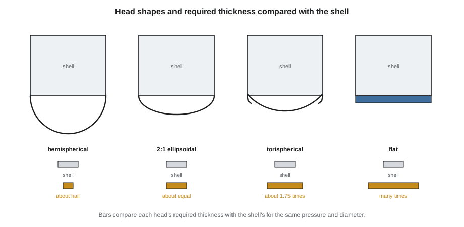
Formed heads have a short cylindrical straight flange at the edge, so the seam to the shell is a straight butt weld clear of the curve. Forming thins the plate, especially at the knuckle, so heads are ordered with a minimum thickness after forming, and the shop checks it with an ultrasonic gauge when the heads arrive. The code below compares the required thicknesses of the shell and the three formed head shapes for V-412's design pressure, and then checks one of the nozzle openings.
# V-412 knockout drum: shell and head thickness, and a simplified opening check (metric, illustrative)
P = 1.7          # design pressure, MPa
D = 1_800          # inside diameter, mm
S = 138          # allowable stress at design temperature, MPa
E = 1.0          # joint efficiency with full radiography
CA = 3.0        # corrosion allowance, mm
R = D / 2

shell = P * R / (S * E - 0.6 * P)                 # cylindrical shell, circumferential stress
ellip = P * D / (2 * S * E - 0.2 * P)             # 2:1 ellipsoidal head
hemi = P * R / (2 * S * E - 0.2 * P)              # hemispherical head
tori = 0.885 * P * D / (S * E - 0.1 * P)          # torispherical (crown radius = D, 6% knuckle)
print("Required thickness, then with corrosion allowance:")
for name, t in [("shell", shell), ("2:1 ellipsoidal head", ellip), ("hemispherical head", hemi), ("torispherical head", tori)]:
    print(f"  {name:22} {t:.1f} -> {t + CA:.1f} mm")

# Opening for nozzle N2: area replacement idea (simplified)
d = 300             # finished opening, corroded, mm
t = 16 - CA         # shell as built, corroded
tn = 12 - CA       # nozzle neck wall, corroded
trn = P * (d / 2) / (S - 0.6 * P)
A_req = d * shell
A1 = d * (t - shell)                       # extra shell thickness near the opening
A2 = 5 * (tn - trn) * min(t, tn)           # extra nozzle wall within the limit
A4 = 10 ** 2                            # two fillet welds, leg squared over two each
have = A1 + A2 + A4
print(f"Area to replace {A_req:,.0f} mm2; shell {A1:,.0f}, nozzle {A2:,.0f}, welds {A4:,.0f} = {have:,.0f} mm2")
if have < A_req:
    tp = 13
    width = (A_req - have) / tp
    print(f"Short by {A_req - have:,.0f} mm2: a {tp} mm pad needs about {width:.0f} mm of width,")
print(f"so the pad outside diameter is about {d + 2 * 12 + width:.0f} mm")Required thickness, then with corrosion allowance: shell 11.2 -> 14.2 mm 2:1 ellipsoidal head 11.1 -> 14.1 mm hemispherical head 5.6 -> 8.6 mm torispherical head 19.6 -> 22.6 mm Area to replace 3,351 mm2; shell 549, nozzle 321, welds 100 = 970 mm2 Short by 2,380 mm2: a 13 mm pad needs about 183 mm of width, so the pad outside diameter is about 507 mm
V-412's shell needs about 14.2 mm (0.578 in) with the corrosion allowance, so the shop used 16 mm (5/8 in) plate. Its 2:1 ellipsoidal heads need about the same, and they were ordered at 16 mm (5/8 in) minimum after forming. A torispherical head would have needed about 23 mm (0.92 in), which is why the designer chose the ellipsoidal shape.
Nozzles and reinforcement
Every opening in a shell weakens it, because the metal that would have carried the stress across the hole is gone. The code's approach for most openings is area replacement: the cross-sectional area of metal removed from the shell, the opening's diameter times the shell's required thickness, must be replaced by extra metal close to the opening. Some of that metal is already there, in the shell's extra thickness above what it needs, in the nozzle neck's extra wall and in the attachment welds. If those are not enough, a reinforcing pad, a ring of plate around the nozzle welded to the shell, makes up the rest.
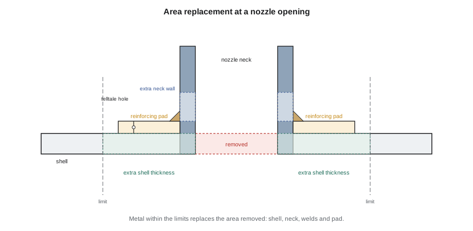
The check in the code above is simplified, but it shows why nozzle N2 needs a pad. Its 300 mm (12 in) opening removes about 3,350 mm2 (5.4 in2) of required metal; the shell, neck and welds give back less than a third of that, so a pad about 13 mm (1/2 in) thick and roughly 510 mm (21 in) in outside diameter is needed. The drawing calls for a 520 mm (21 1/2 in) pad. Reinforcing pads have a small telltale hole, drilled and tapped, that lets air out when the pad is welded and is used later to test the pad's welds with low-pressure air and soap solution. The hole is left open in service, so a leak through the shell under the pad shows itself instead of building up pressure behind the pad.
| Nozzle part | What it is | Fitting notes |
|---|---|---|
| Neck | Pipe or rolled plate that passes through the shell | Set-in or set-on as the drawing shows; projection measured from the vessel centre line |
| Flange | Weld neck, slip-on or other type, rated by pressure class | Bolt holes straddle the centre lines unless the drawing says otherwise |
| Reinforcing pad | Ring of plate around the neck | Same material as the shell; telltale hole; fitted tight to the shell |
| Gussets or braces | Support for small nozzles on vibrating lines | Only where the drawing shows them |
| Manway | Large nozzle with a bolted cover and davit | Davit swing and cover clearance checked before welding |
Flanges are almost always to the standard ASME B16.5 for pipe sizes up to 600 mm nominal, and are made in pressure classes such as 150, 300 and 600, each with a pressure and temperature rating. The fitter's checks on a nozzle are orientation, measured as an angle around the shell from the drawing's zero, elevation from a datum line, projection from the vessel's centre line to the flange face, the flange face being square to the nozzle axis and the bolt holes straddling the centre lines. On V-412, Kiera checks the projections of the four nozzles with a tape and a level from the shell's scribed centre lines, and the bolt hole orientation with a flange level.
Supports, internals and the nameplate
Vertical vessels like V-412 stand on a skirt, a cylinder welded to the bottom head with a base ring and anchor bolt chairs, or on legs or lugs. Horizontal vessels sit on two saddles, one fixed and one sliding, so the vessel can grow, just like a packaged boiler. Internals depend on the service: V-412 has an inlet diverter that slows the incoming gas and a mesh pad near the top that catches liquid droplets before the gas leaves. Internals are bolted to clips welded to the shell, and any welding to the shell must be done before the vessel is tested and heat treated, never after.
When the vessel is finished, tested and inspected, the manufacturer attaches a nameplate stamped with the code symbol, the manufacturer's name, the serial number, the year built, the maximum allowable working pressure at its temperature, the minimum design metal temperature and the extent of radiography. In Alberta, the CRN is stamped on it too. The manufacturer's data report, a U-1 or U-1A form signed by the inspector, records the vessel's construction and goes to the owner. In the United States, the vessel is usually registered with the National Board. The nameplate is the vessel's identity for the rest of its life; it must never be painted over or removed.
Worked problem
Shell thickness
A vessel has an inside diameter of 1,200 mm (48 in), a design pressure of 1.0 MPa (150 psi), an allowable stress of 138 MPa (20,000 psi), full radiography and a corrosion allowance of 3 mm (1/8 in). What thickness does the shell need?
Show solution
- Inside radius: 600 mm.
- Required thickness: 1.0 × 600 ÷ (138 × 1.0 − 0.6 × 1.0) = 600 ÷ 137.4 = 4.37 mm.
- With corrosion allowance: 4.37 + 3 = 7.37 mm.
Answer: About 7.4 mm; the shop would use 8 mm plate or the next size its practice and the mill tolerance require.
Heat treatment and the order of work
Some vessels must be stress relieved by postweld heat treatment after welding, because of their thickness, their material or their service. V-412's shell is thin enough and its service mild enough that it does not need heat treatment, but many refinery vessels do. When they do, the order of work is fixed: all welding to the pressure parts, including clips, pads and nameplate brackets, is finished first; the vessel is heat treated; and then it is hydrostatically tested. Welding after heat treatment would undo it, so a forgotten clip means another heat treatment.
Common mistakes
MistakeFitting a smaller reinforcing pad because it is in the scrap rack.
InsteadPads are sized by calculation; fit only what the drawing calls for.
MistakePlugging a reinforcing pad's telltale hole.
InsteadLeave it open; it shows leaks and is used to test the pad welds.
MistakeWelding a clip to a vessel after heat treatment or the hydrostatic test.
InsteadAll welding to pressure parts is finished before heat treatment and testing.
MistakePainting over the nameplate.
InsteadMask the nameplate; it carries the vessel's legal identity.
MistakeMeasuring nozzle projection from the shell surface.
InsteadProjection is measured from the vessel's centre line unless the drawing says otherwise.
Summary and key terms
- Hoop stress in a cylinder is twice the longitudinal stress, so shell thickness is set by the hoop stress.
- The required thickness depends on pressure, radius, allowable stress and joint efficiency; corrosion allowance and forming thinning are added.
- Hemispherical heads need about half the shell thickness, 2:1 ellipsoidal heads about the same, torispherical heads more and flat heads far more.
- Openings are reinforced by area replacement from extra shell, neck wall, welds and pads.
- Fitters check nozzle orientation, elevation, projection, flange squareness and bolt hole orientation.
- The nameplate and the manufacturer's data report record the vessel's construction for its whole life.
- Hoop stress
- The circumferential stress in a cylinder under pressure, twice the longitudinal stress.
- Joint efficiency
- A factor that reduces the allowed stress at a weld according to how fully it is examined.
- Corrosion allowance
- Extra thickness added to allow for metal loss in service.
- 2:1 ellipsoidal head
- A head shaped like half an ellipse with a depth of a quarter of the diameter.
- Reinforcing pad
- A ring of plate around a nozzle that replaces metal removed by the opening.
- Telltale hole
- A small hole through a pad or liner that vents it and reveals leaks.
Practice problems
Work each problem on paper first, then reveal the answer to check.
Why does the longitudinal seam of a shell carry more stress than a circumferential seam?
Show answer
It carries the hoop stress, which is twice the longitudinal stress.
Which formed head needs the least thickness for a given pressure?
Show answer
The hemispherical head, about half the shell's thickness.
A nozzle opening is 200 mm across in a shell whose required thickness is 10 mm. How much area must be replaced?
Show answer
200 × 10 = 2,000 mm2.
What information does a vessel's nameplate carry?
Show answer
The code symbol, manufacturer, serial number, year, MAWP at temperature, minimum design metal temperature, extent of radiography and, in Canada, the CRN.
Lesson quiz · 5 questions
Score 60% or more to complete this lesson.
Create a free account to save your progress, take quizzes and earn a certificate.