
BAS-340 · Lesson 5 of 12 · 24 min
Fire alarm interfaces and smoke control
▶ Video coming soon A video version of this lesson is on the way.
Ninefield's annual fire alarm test was held early on Sunday, October 18, when the building was nearly empty. Signalpoint Fire Systems, the building's fire alarm contractor, ran it, with their technician Dorian Strathy at the panel and a second technician on the floors. Ilona Vescovi had asked Quillon to send someone to watch the building automation side, and Prakash went. He did not touch anything. His job, he told Callie afterward, was to stand at the front end with a notebook and write down what the BAS showed while the fire alarm system did its work, because that is the only way to find out whether the two systems tell the same story.
What a fire alarm system does
A fire alarm system detects fire and smoke, warns the occupants, calls for help and starts the building's automatic responses. Its parts are defined by the codes and standards that govern it.
- Initiating devices: smoke and heat detectors, manual pull stations, sprinkler water flow switches, and duct smoke detectors in air handlers.
- The control unit, the fire alarm panel, which processes signals, supervises every circuit and battery, and records events.
- Notification appliances: horns, speakers and strobes.
- Off-premises signalling to a signal receiving centre that calls the fire department.
- Supervisory signals for conditions such as a closed sprinkler valve, and trouble signals for faults in the system itself.
- Outputs to other systems, often called ancillary or emergency control functions: stopping fans, closing dampers, releasing door locks and hold-open devices, recalling elevators, and starting smoke control.
In Ontario, fire alarm systems are required by the building code for many buildings and installed to CAN/ULC-S524. Each new or modified installation is verified to CAN/ULC-S537 before it is relied on, and the system is inspected and tested in service under the Ontario Fire Code, which from January 1, 2026 references the 2019 editions of CAN/ULC-S536 for inspection and testing and S537 for verification. Control units are listed to CAN/ULC-S527. All of this work is done by qualified fire alarm technicians, most of whom hold registration from the Canadian Fire Alarm Association, which specifications commonly require.
None of that work is controls work. A controls technician does not install, program, disconnect, bypass, test or modify any part of a fire alarm system, and does not ask a fire alarm technician to do so for the BAS's convenience. That rule is not a matter of company policy; it follows from the codes, which make the fire alarm system the responsibility of qualified people working under the fire code.
How the fire alarm system reaches the HVAC
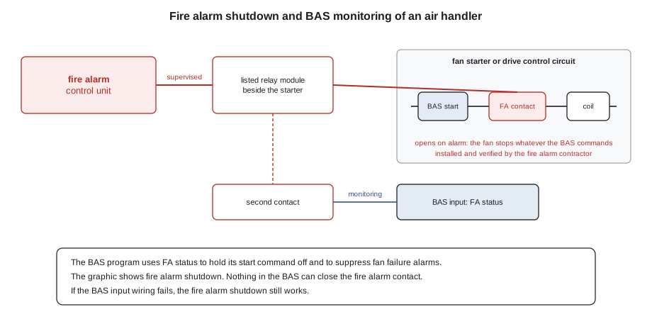
At Ninefield, as in most buildings of its age, the fire alarm system stops the air handlers directly. A relay controlled by the fire alarm panel has a contact wired into the control circuit of each fan's starter or drive. When the panel goes into alarm, the relay opens the circuit and the fan stops, whatever the BAS is commanding. This connection is hardwired, supervised by the fire alarm system up to the relay, and verified by the fire alarm contractor. The relays and modules used for these functions are listed for use with the fire alarm panel, and the standards place requirements on how they are installed, including keeping them close to the equipment they control.
The BAS gets its own, separate signal: a second contact on the relay, or a separate monitoring output, wired to a BAS binary input. That input tells the BAS that the fan has stopped because of the fire alarm, so that its programs, graphics and alarms can respond sensibly. It is a monitoring point. If the BAS input wiring breaks, the fire alarm shutdown still works.
Newer fire alarm panels can also share their status with a BAS over a network, usually through a gateway that presents points as BACnet objects. That link is useful for graphics and operator awareness. It is read only, it is not part of the fire alarm system's required functions, and it does not replace the hardwired monitoring contacts where the design calls for them.
Rules for the BAS side
Prakash's rules for any BAS work near a fire alarm interface fit on one card.
- Fire alarm functions stay in the fire alarm system. The BAS never performs, duplicates, delays or overrides one.
- The BAS monitors through listed relays or interfaces provided by the fire alarm contractor, and only reads.
- A BAS program must never restart or countermand equipment the fire alarm system has stopped while the fire alarm signal is active. The FA status input holds the program's start command off, even though the hardwired contact would stop the fan anyway.
- The BAS shows the true reason. While FA status is active, fan failure and low airflow alarms are suppressed, and the graphic says fire alarm shutdown.
- Fire alarm wiring that passes through a BAS panel is labeled and not disturbed. If BAS work requires moving it, the fire alarm contractor does it and re-verifies the function.
- After the fire alarm system is reset, the BAS restarts equipment in a controlled order, not all at once.
What the test showed
The test on October 18 checked every initiating zone and every output. Prakash's notes recorded the BAS view of the penthouse air handlers. Every fan stopped within seconds of the first alarm, as the relays opened their circuits, and every air handler but one showed fire alarm shutdown on the front end. The exception was AHU-2, which showed a fan failure alarm instead, and its graphic showed the fan commanded on and not running.
The fault was in the BAS, not the fire alarm system. When Sophie rewrote the penthouse air handler program in 2022, the 1998 monitoring contact for AHU-2's fire alarm relay had been listed on the points list as a spare input, because its tag had faded and nobody had traced it. So the program never knew why AHU-2 had stopped. The shutdown itself worked perfectly; only the story the BAS told the operator was wrong. An operator chasing a fan failure during a real alarm would have been wasting time on the wrong problem.
Prakash traced and labeled the contact the next morning, Monday, October 19, while he was at Ninefield for the chiller changeover, and Sophie mapped it as AHU-2 FA status that afternoon, with the same alarm suppression and start-command hold as the other air handlers. Signalpoint did not need to be involved, because nothing on their side of the relay was touched; Prakash still sent Dorian a note of what had been changed, so that the next test would check it.
The second finding came at the end of the test. When the panel was reset, the BAS programs restarted every supply and return fan within the same minute, because each program saw its FA status clear at the same moment. On a Sunday with the building empty that did no harm, but on a weekday it would put a step of several hundred kilowatts on the demand meter and slam every VAV damper at once. Sophie added a restart inhibit to the spring 2027 retro-commissioning draft: after a fire alarm reset or a power restoration, the air handlers restart one at a time, 60 s apart.
Worked problem
A staggered restart after reset
Suppose four air handling units are to restart in turn after a fire alarm reset. Each supply fan's drive ramps up over 45 s, and the program waits for airflow proof before starting the next unit. If the restart interval is 60 s, how long until all four are running, and what is the first unit's head start over the last?
Show solution
- Unit 1 starts at 0 s, unit 2 at 60 s, unit 3 at 120 s and unit 4 at 180 s.
- Unit 4 reaches speed at 180 + 45 = 225 s.
- The first unit's head start over the last is 180 s.
Answer: All four are running about 225 s, under four minutes, after the reset. The order matters too: the unit serving the most critical floors starts first, and the sequence states the order.
Smoke control
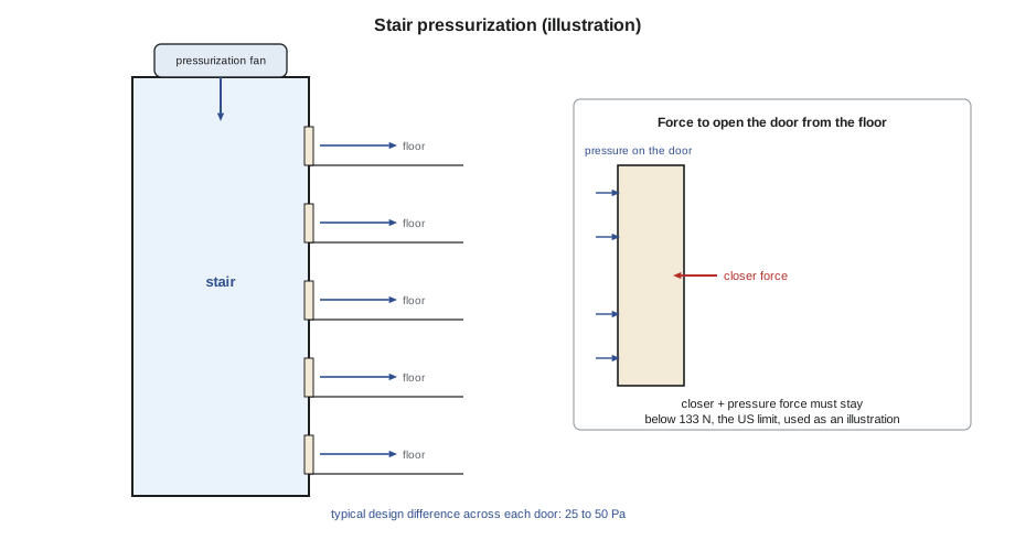
Smoke kills more people in fires than flames do, and smoke control systems exist to keep escape routes and refuge areas tenable while people leave and firefighters work. They do it with pressure differences and airflows: by pressurizing exit stairs so that smoke cannot enter them, by pressurizing the floors around a fire floor and exhausting the fire floor, or by exhausting smoke from the top of an atrium.
| Approach | How it works | Typical equipment |
|---|---|---|
| Stair pressurization | Supply air into the stair keeps it at a higher pressure than the floors, so smoke flows away from the doors | Dedicated stair fans, relief dampers or variable speed control, pressure sensing |
| Zoned smoke control | The fire floor is exhausted and the floors above and below are pressurized | Often the building's own air handlers and dampers in special modes |
| Atrium and large-space exhaust | Smoke is exhausted from the top of a tall space to keep the smoke layer above people | Exhaust fans, makeup air openings |
| Elevator hoistway pressurization | Keeps smoke out of elevator shafts used by firefighters | Dedicated fans |
A smoke control system is dedicated when its fans and dampers do nothing else, and non-dedicated when it uses the normal HVAC equipment in special modes. Non-dedicated systems are where the BAS meets smoke control most often, because the same air handlers and dampers that the BAS runs every day must be driven to smoke control positions in an emergency.
Where a building uses its automation system to carry out smoke control, the controllers, the network and the firefighters' control panel must be listed as smoke control system equipment. In Canada that listing is to ULC/ORD-C100 together with UL 864, usually shown as the UUKLC category; the design follows the building code's requirements, which for high buildings in Ontario include specific smoke control measures, and the system is verified and tested as part of the fire alarm verification and the integrated testing of CAN/ULC-S1001.
A listed smoke control system includes a firefighter's smoke control station, a panel near the fire department's entrance where firefighters can see the state of every smoke control fan and damper and take manual control. Commands from that panel have the highest priority in the system. Where smoke control runs through BACnet, those commands are written at the life-safety priorities, 1 or 2, and every normal program and operator command sits below them. Quillon's convention of priority 2 for automatic smoke control commands comes from such buildings; at Ninefield, where the smoke control equipment is started directly by the fire alarm system, there are no BAS smoke control commands at all.
Ninefield's smoke control dates from its design for a high building in 1979, with later changes. Each of the two exit stairs has a dedicated pressurization fan started by fire alarm relays, and the air handlers stop. The BAS monitors the two stair fans' run status through separate contacts and shows them on a life-safety page that operators can view but not command. Nothing on that page is a BAS output.
Worked problem
Why stair pressure has an upper limit
A stair door is 0.90 m wide and 2.10 m high (3.0 ft wide and 7.0 ft high), with its handle 0.075 m (0.25 ft) from the latch edge. The closer needs 40 N (9 lbf) at the handle. With the stair pressurized to 50 Pa (0.20 in. w.c.) above the floor, about what force is needed to open the door from the floor side? Compare it with the 133 N (30 lbf) limit in US codes, used here as an illustration. (Design values are the smoke control engineer's; this is a check of the idea.)
Show solution
- Door area A = 0.90 × 2.10 = 1.89 m².
- Force from pressure at the handle = (W × A × ΔP) ÷ (2 × (W − d)) = (0.90 × 1.89 × 50) ÷ (2 × 0.825) = 85.05 ÷ 1.65 = 51.5 N.
- Total = 40 + 51.5 = 91.5 N.
Answer: About 92 N, below the 133 N illustration limit. Doubling the pressure to 100 Pa would add another 51.5 N and reach about 143 N, too hard to open. That is why stair pressurization systems control the pressure, with relief or variable speed, rather than simply blowing as hard as they can.
Smoke control also shapes how BAS equipment is chosen and maintained. Dampers that are part of a smoke control system are smoke dampers or combination fire and smoke dampers, listed for the purpose, with actuators and end switches that the smoke control system uses to prove their position. They are tested on the schedule the fire code sets. A controls technician replacing a damper actuator on a non-dedicated smoke control system is working on life-safety equipment, and the replacement must be the listed type and the function retested with the people responsible for the smoke control system.
Common mistakes
MistakeTreating the BAS fire alarm input as a way to perform a fire alarm function.
InsteadThe input is for monitoring only; the fire alarm system performs its functions through its own hardwired outputs.
MistakeDisturbing fire alarm wiring that passes through a BAS panel during a controller replacement.
InsteadLeave it, label it, and have the fire alarm contractor move and re-verify it if it must change.
MistakeLeaving fan failure alarms active during a fire alarm shutdown.
InsteadMap FA status and suppress the alarms so the operator sees the true reason.
MistakeRestarting every air handler at once after a fire alarm reset.
InsteadRestart in a stated order with a time interval.
MistakeReplacing a smoke damper actuator with any spring-return actuator that fits.
InsteadUse the listed type and retest the smoke control function with the responsible parties.
Summary and key terms
- Fire alarm systems detect, warn, call for help and start automatic responses; they are installed, verified, tested and modified only by qualified fire alarm technicians under the fire code.
- Fan shutdown on fire alarm is a hardwired contact in the fan circuit; the BAS gets a separate monitoring contact.
- BAS programs hold their start commands off and suppress misleading alarms while FA status is active.
- After reset, equipment restarts in a controlled order.
- Smoke control uses pressure and airflow to keep escape routes clear; dedicated systems have their own fans, non-dedicated systems use the HVAC.
- A BAS that performs smoke control must be listed for it, with a firefighter's control panel at the highest priority.
- Stair pressure is limited by the force needed to open exit doors.
- Fire alarm control unit
- The panel that processes fire alarm signals, supervises circuits and controls outputs.
- Relay module
- A listed fire alarm output device whose contacts switch other equipment, such as a fan circuit.
- FA status input
- A BAS input that monitors a fire alarm relay contact, for information only.
- Smoke control system
- A system that uses fans and dampers to manage smoke movement in a fire.
- Dedicated smoke control system
- A smoke control system whose equipment serves no other purpose.
- Non-dedicated smoke control system
- A smoke control system that uses the normal HVAC equipment in special modes.
- Firefighter's smoke control station
- The panel from which firefighters monitor and manually control the smoke control system.
- UUKL
- The UL listing category for smoke control system equipment.
Practice problems
Work each problem on paper first, then reveal the answer to check.
Five air handlers restart 45 s apart, each taking 40 s to reach speed. When is the last at speed?
Show answer
4 × 45 + 40 = 220 s.
A door is 0.9 m by 2.0 m. What is its area?
Show answer
1.8 m².
With W = 0.9 m, d = 0.075 m, A = 1.8 m² and ΔP = 40 Pa, what is the pressure force at the handle?
Show answer
(0.9 × 1.8 × 40) ÷ 1.65 = 39.3 N.
Who restores a fire alarm wire that must be moved in a BAS panel?
Show answer
The fire alarm contractor, who also re-verifies the function.
What should the AHU graphic say while FA status is active?
Show answer
Fire alarm shutdown.
Lesson quiz · 5 questions
Score 60% or more to complete this lesson.
Create a free account to save your progress, take quizzes and earn a certificate.