
AUTO-120 · Lesson 7 of 12 · 20 min
Engine measurement and precision tools
For three days the training engine has been coming apart on bay 5's bench. The pistons are out, numbered and laid in order on a clean towel with their rods and caps; the crankshaft is resting in a V-block stand; the bearing shells are taped to a sheet of cardboard labelled with their positions. Marty sets down a wooden case of tools Kiran has not used yet: a dial bore gauge, a set of telescoping gauges, an outside micrometer set from 25 to 100 mm, a dial indicator on a magnetic base, and a box of plastic gauge strips. “Now we find out whether this engine could go back together, or whether it needs machining,” he says. “The only way to know is to measure.”
Engine work depends on measurements that are often smaller than the thickness of a sheet of paper. This lesson explains the precision tools technicians use, how to measure cylinder bores, crankshaft journals, bearing clearances, crankshaft end play and piston ring gaps, and how to compare the results with specifications. AUTO-110 introduced reading calipers and micrometers; this lesson puts them to work.
Before measuring
Three conditions make engine measurements trustworthy. The parts must be clean, because a film of old oil or carbon is thicker than many of the clearances being measured. They must be at room temperature, about 20 °C, because the specifications assume it and aluminum and iron expand at different rates, as Lesson 2 showed. And the tools must be checked: a micrometer is zeroed against its standard, and a bore gauge is set against a micrometer or a setting ring at the nominal size before use. Readings are written down as they are taken, on a sheet laid out by cylinder and position, so nothing depends on memory.
Kiran also learns the habit of measuring twice. If two readings of the same place disagree, the tool is being used inconsistently, usually because it is tilted or pressed too hard, and a third reading decides. A micrometer's ratchet or friction thimble gives the same light pressure every time; a bore gauge is rocked gently until the dial reaches its turning point, the smallest reading, which is the true diameter.
Precision tools
| Tool | What it measures | How it is used |
|---|---|---|
| Outside micrometer | Diameters of journals, pistons, valve stems | Spindle closed with the ratchet; read sleeve and thimble |
| Telescoping gauge | Inside diameters with a micrometer | Expanded in the bore, locked, withdrawn and measured |
| Dial bore gauge | Bore size, taper and out-of-round directly | Set to nominal, rocked in the bore to the turning point |
| Dial indicator | Movement: end play, runout, lift | Mounted on a magnetic base with its plunger on the part |
| Feeler gauges | Gaps: ring end gap, valve clearance, warpage | The blade that slides with light drag gives the gap |
| Plastic gauge | Bearing oil clearance | Crushed between journal and bearing; its width is read |
| Straightedge | Flatness of decks and heads | Laid on edge; feeler gauge under it |
Micrometers read to one hundredth of a millimetre on the thimble, and those with a vernier scale on the sleeve read to one thousandth. A dial bore gauge typically reads to one thousandth of a millimetre per graduation. Feeler gauges come in sets of blades, each marked with its thickness.
Measuring a cylinder bore
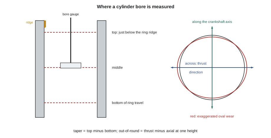
A cylinder wears unevenly. The top ring presses hardest against the wall just below the top of its travel, where the piston stops and reverses with full combustion pressure behind it, so the bore wears most there and least at the bottom, where the ring barely presses. The result is taper: the bore is larger at the top than at the bottom. The piston also pushes harder against one side of the wall, the thrust side, on the power stroke, so the bore wears into an oval. The difference between the largest and smallest diameters at one height is the out-of-round.
Above the top of the ring travel there is often a small ridge of unworn metal, the ring ridge. On an engine that has worn a great deal it can be felt with a fingernail, and it must be removed with a ridge reamer before the pistons are pushed out the top, or the rings will catch on it and break the ring lands.
The bore is measured at three heights: just below the ring ridge, at the middle, and near the bottom of the ring travel. At each height it is measured in two directions: along the crankshaft axis and across it, in the thrust direction. The difference between the top and bottom readings in the thrust direction is the taper; the difference between the two directions at each height is the out-of-round. Both are compared with the limits in the service information, and the largest reading is compared with the maximum bore size.
# Training engine: bore taper and out-of-round from dial bore gauge readings
nominal = 86.000
taper_limit, oor_limit, max_bore = 0.050, 0.030, 86.060        # mm (illustrative)
# readings for each cylinder: [top, middle, bottom] in the thrust direction and along the crankshaft axis
bores = {
    1: ([86.042, 86.025, 86.011], [86.020, 86.016, 86.009]),
    2: ([86.048, 86.028, 86.012], [86.022, 86.018, 86.010]),
    3: ([86.066, 86.034, 86.012], [86.031, 86.020, 86.010]),
    4: ([86.040, 86.024, 86.010], [86.021, 86.015, 86.009]),
}
for cyl, (thrust, axial) in bores.items():
    taper = thrust[0] - thrust[2]
    oor = max(t - a for t, a in zip(thrust, axial))
    biggest = max(thrust + axial)
    ok = taper <= taper_limit and oor <= oor_limit and biggest <= max_bore
print(f"cyl {cyl}: largest {biggest:.3f}, taper {taper:.3f}, out-of-round {oor:.3f} mm {'within limits' if ok else 'OUT OF LIMITS'}")cyl 1: largest 86.042, taper 0.031, out-of-round 0.022 mm within limits cyl 2: largest 86.048, taper 0.036, out-of-round 0.026 mm within limits cyl 3: largest 86.066, taper 0.054, out-of-round 0.035 mm OUT OF LIMITS cyl 4: largest 86.040, taper 0.030, out-of-round 0.019 mm within limits
Cylinder 3 has worn more than the others, beyond its taper limit and the maximum bore size. Marty explains what that means for a real engine: the block would have to be bored oversize by a machine shop and fitted with oversize pistons and rings, or, if the manufacturer does not offer oversizes for an aluminum block with thin liners, replaced. A bore that is within its limits but glazed, polished smooth by the rings, is honed with a fine abrasive tool to put back the crosshatch pattern of fine scratches that holds oil and lets new rings seat.
Piston rings and piston clearance
A ring's end gap is checked by pushing the ring squarely into the bore with an upside-down piston, to a point in the ring travel the service information specifies, usually near the bottom where the bore is least worn, and sliding feeler blades into the gap. Too small a gap lets the ends butt together when the ring heats up, which can scuff the cylinder or break the ring; too large lets blow-by through. New rings may need their ends filed to reach the specified gap, filing only the end, squarely, and removing the burr.
Piston-to-bore clearance is found by measuring the piston's skirt diameter with a micrometer at the point the service information specifies, usually at right angles to the pin and a set distance from the bottom of the skirt, and subtracting it from the bore diameter measured in the thrust direction. Ring side clearance, the gap between the ring and the side of its groove, is checked with a feeler gauge while the ring sits in its groove; a worn groove lets the ring twist and pump oil.
# Piston ring end gaps measured in the bore (training engine, illustrative limits)
limits = {"top": (0.20, 0.50), "second": (0.35, 0.65), "oil rail": (0.20, 0.70)}   # mm
gaps = {1: {"top": 0.38, "second": 0.52, "oil rail": 0.45},
        3: {"top": 0.62, "second": 0.71, "oil rail": 0.58}}
for cyl, rings in gaps.items():
    for ring, gap in rings.items():
        lo, hi = limits[ring]
        status = "OK" if lo <= gap <= hi else ("too small: file the ends" if gap < lo else "too large: replace the rings")
print(f"cyl {cyl} {ring:<9} {gap:.2f} mm (limits {lo:.2f} to {hi:.2f}) {status}")cyl 1 top 0.38 mm (limits 0.20 to 0.50) OK cyl 1 second 0.52 mm (limits 0.35 to 0.65) OK cyl 1 oil rail 0.45 mm (limits 0.20 to 0.70) OK cyl 3 top 0.62 mm (limits 0.20 to 0.50) too large: replace the rings cyl 3 second 0.71 mm (limits 0.35 to 0.65) too large: replace the rings cyl 3 oil rail 0.58 mm (limits 0.20 to 0.70) OK
These are the engine's old rings, so their gaps have grown with wear. Cylinder 3's top and second rings are beyond the limit, which agrees with its worn bore: worn rings in a worn bore pass blow-by and burn oil, and on a running engine they would show up in a compression and leak-down test as Lesson 10 describes.
Crankshaft journals and bearing clearance
Each main and rod journal is measured with an outside micrometer at two points along its length and in two directions at each point, at right angles. The differences give the journal's taper and out-of-round, and the smallest reading is compared with the minimum diameter. A journal that is under size, tapered, out of round or scored is reground by a machine shop to a standard undersize and fitted with matching undersize bearings, or the crankshaft is replaced.
Bearing oil clearance can be measured two ways. The first is to measure the bearing's inside diameter, with the shells installed and the cap tightened to specification, using a bore gauge or telescoping gauge, and subtract the journal diameter. The second, quicker and common in repair shops, uses plastic gauge: a thin, soft plastic thread of accurately known diameter. A strip is laid across the clean, dry journal, the cap and bearing are installed and tightened to specification without turning the crankshaft, and then removed. The plastic has been crushed into a flat band whose width depends on the clearance, and the width is compared with the scale printed on the package. The band is wiped off afterwards; it is oil-soluble.
# Bearing clearance: plastic gauge readings and journal micrometer readings (illustrative)
spec = (0.018, 0.042)            # main bearing oil clearance, mm
plastic_gauge = {1: 0.025, 2: 0.025, 3: 0.038, 4: 0.051, 5: 0.025}       # width read from the scale
journals = {1: ((54.987, 54.986), (54.987, 54.987)), 3: ((54.982, 54.974), (54.981, 54.975))}    # diameter at front and rear, two directions each
for main, clr in plastic_gauge.items():
    print(f"main {main}: clearance {clr:.3f} mm ->", "OK" if spec[0] <= clr <= spec[1] else "outside specification")
for main, (front, rear) in journals.items():
    taper = abs(max(front) - max(rear))
    oor = max(abs(front[0] - front[1]), abs(rear[0] - rear[1]))
print(f"journal {main}: smallest {min(front + rear):.3f} mm, taper {taper:.3f}, out-of-round {oor:.3f}")main 1: clearance 0.025 mm -> OK main 2: clearance 0.025 mm -> OK main 3: clearance 0.038 mm -> OK main 4: clearance 0.051 mm -> outside specification main 5: clearance 0.025 mm -> OK journal 1: smallest 54.986 mm, taper 0.000, out-of-round 0.001 journal 3: smallest 54.974 mm, taper 0.001, out-of-round 0.008
Main bearing 4 is beyond its clearance limit, and journal 3 is slightly out of round. Kiran looks at the old bearing shells taped to the cardboard. The shells from main 4 show a dull grey band worn through the bearing alloy in the middle, and those from main 3 show fine scratches from dirt in the oil. Reading worn bearings is part of measuring: wear in the centre suggests a lack of oil, scratches suggest dirt, and wear at the edges suggests a tapered journal or a bent rod.
Crankshaft end play is measured with a dial indicator mounted on the block, its plunger against the end of the crankshaft. The crankshaft is pried fully toward the rear, the indicator is zeroed, and the crankshaft is pried fully forward; the reading is the end play. Typical values are about 0.05 to 0.25 mm. Too much end play, usually from a worn thrust bearing, can make a manual transmission's clutch pedal feel spongy and disturb crankshaft position sensor readings; too little can make the thrust bearing seize. Connecting rod side clearance, the gap between the rod and the crankpin's cheek, is checked with a feeler gauge.
Recording and deciding
A measurement sheet is a decision tool. Marty's rule is that numbers are compared with specifications, never with what feels right, and that a part is reused only if every measurement is within its limits. When some measurements are out of limits, the technician lists the work needed to bring the engine back to specification, such as machining, oversize parts or replacement parts, and with the service advisor, prices it against the alternatives, such as a remanufactured engine or a used one from a dismantler. For a customer engine, that comparison becomes the estimate.
Worked problem
What would it take to rebuild the training engine?
From the measurements in this lesson, list what a machine shop and parts supplier would need to provide to rebuild the training engine to specification.
Show solution
- Cylinder 3 is beyond the taper and maximum bore limits, so all four cylinders must be bored to the same oversize, if the manufacturer offers one, with oversize pistons and rings; otherwise the block must be replaced.
- Because the cylinders will be bored, new rings are needed for all pistons; the worn ring gaps on cylinder 3 confirm it.
- Main bearing 4 has too much clearance and journal 3 is out of round, so the crankshaft must be reground to an undersize with matching undersize bearings, or replaced.
- The head needs the springs and shims identified in Lesson 4 and a check of the guides and seats.
- With machining, parts and labour together, a remanufactured engine may cost less; on a real customer engine the advisor would price both.
Answer: Bore and oversize pistons or a new block, a reground or new crankshaft with matching bearings, new rings, and head work; then compare with a remanufactured engine.
Common mistakes
MistakeMeasuring a warm or dirty part.
InsteadClean the part and let it reach room temperature.
MistakeUsing a bore gauge without setting it to nominal.
InsteadSet it against a micrometer or setting ring first.
MistakeTurning the crankshaft with plastic gauge installed.
InsteadTighten the cap to specification and remove it without turning.
MistakeChecking ring gap at the top of a worn bore.
InsteadSquare the ring in the bore at the depth specified, usually low in the ring travel.
MistakeComparing readings with what seems reasonable.
InsteadCompare every reading with the specification and record it.
Summary and key terms
- Clean, room-temperature parts and checked tools give trustworthy measurements; record every reading.
- Bores are measured at three heights and two directions; wear is greatest at the top in the thrust direction.
- Taper is the top-to-bottom difference; out-of-round is the difference between directions at one height.
- Ring end gap is measured with the ring squared in the bore; piston clearance is bore minus skirt diameter.
- Bearing clearance is measured with plastic gauge or by subtracting journal from bearing diameter.
- End play is measured with a dial indicator; out-of-limit results decide whether to machine, replace or exchange.
- Taper
- The difference in diameter between the top and bottom of a bore or the ends of a journal.
- Out-of-round
- The difference between the largest and smallest diameters at one position.
- Ring ridge
- Unworn metal at the top of a cylinder above the ring travel.
- Ring end gap
- The gap between the ends of a piston ring installed in the bore.
- Plastic gauge
- A crushable plastic thread used to measure bearing oil clearance.
- End play
- The front-to-rear movement of a shaft between its thrust surfaces.
- Thrust side
- The side of the cylinder the piston presses hardest against on the power stroke.
Practice problems
Work each problem on paper first, then reveal the answer to check.
A bore reads 86.045 mm at the top and 86.012 mm at the bottom in the thrust direction. What is its taper?
Show answer
0.033 mm.
At one height a bore reads 86.040 mm across and 86.020 mm along the crankshaft. What is the out-of-round?
Show answer
0.020 mm.
Why is ring end gap checked near the bottom of the ring travel?
Show answer
The bore is least worn there, so the gap is smallest and a ring that fits there will not butt when hot.
Plastic gauge shows 0.051 mm against a limit of 0.042 mm. What does it mean?
Show answer
The bearing clearance is too large; the bearing and journal need attention.
Lesson quiz · 5 questions
Score 60% or more to complete this lesson.
Create a free account to save your progress, take quizzes and earn a certificate.