
AI-450 · Lesson 4 of 12 · 24 min
Sensors and robot perception
A robot knows only what its sensors tell it, and every sensor is limited: cameras are blinded by glare and darkness, depth sensors struggle with shiny and transparent surfaces, lidars miss thin wires and glass, wheel encoders slip, and inertial sensors drift. Perception is the work of turning these imperfect measurements into a useful picture of the robot and its surroundings: where objects are, what they are, how they can be grasped, and where it is safe to move. Deep learning has transformed robot perception, and large vision foundation models now let robots recognize objects described in plain language, but the geometry of sensors and the physics of their errors still matter. This lesson covers the main proprioceptive and exteroceptive sensors, the camera model, depth sensing by stereo, structured light, time of flight and lidar, the key perception tasks for manipulation and navigation, learned and foundation-model perception, and the practical issues of calibration, synchronization and failure modes.
Proprioceptive sensors
Proprioceptive sensors measure the robot's own state:
- Encoders on motors and joints measure angle or position, from incremental optical encoders with thousands of counts per revolution to absolute encoders that know their position at power-up.
- Inertial measurement units (IMUs) combine accelerometers and gyroscopes (and often magnetometers) to measure linear acceleration and angular velocity, essential for legged robots, drones and vehicle state estimation. Integrating them gives orientation and velocity but errors accumulate (drift).
- Force/torque sensors at the wrist measure the six components of contact force and torque, used in assembly, polishing and safe interaction.
- Joint torque sensors and motor current measurements estimate loads and detect collisions.
- Tactile sensors in fingertips, including vision-based tactile sensors that image a deformable gel, measure contact location, pressure and slip.
Cameras and the pinhole model
Cameras are the richest and cheapest exteroceptive sensors. The pinhole model projects a 3D point (X, Y, Z) in the camera frame to pixel coordinates using the intrinsic matrix K, containing focal lengths in pixels (f_x, f_y) and the principal point (c_x, c_y):
Real lenses add distortion (radial and tangential), modelled with extra parameters and removed by rectification. Intrinsic calibration with a checkerboard or other target estimates K and distortion; extrinsic calibration estimates the camera's pose relative to the robot (Lesson 2). Projection loses depth: every pixel corresponds to a ray, and a point anywhere along that ray produces the same pixel. Recovering 3D structure therefore requires depth sensing, multiple views, motion, or learned depth estimation.
import numpy as np
# Pinhole camera projection and stereo depth uncertainty
fx = fy = 600.0          # focal length in pixels
cx, cy = 320.0, 240.0    # principal point for a 640 x 480 image
K = np.array([[fx, 0, cx], [0, fy, cy], [0, 0, 1]])

points = np.array([[0.0, 0.0, 1.0], [0.2, -0.1, 1.0], [0.2, -0.1, 2.0], [-0.5, 0.3, 4.0]])  # camera frame, m
for p in points:
    u, v, w = K @ p
    print(f"point {p} m -> pixel ({u / w:6.1f}, {v / w:6.1f})")

# Back-projection needs depth: a pixel defines only a ray
u, v = 420.0, 190.0
ray = np.linalg.solve(K, np.array([u, v, 1.0]))
for z in (1.0, 2.0):
    print(f"pixel ({u:.0f}, {v:.0f}) at depth {z} m -> point {np.round(ray * z, 3)} m")

# Stereo: depth Z = f b / d, so a disparity error dd gives depth error about Z^2 dd / (f b)
baseline = 0.12
disparity_error = 0.25   # pixels, typical sub-pixel matching accuracy
for Z in (0.5, 1.0, 2.0, 4.0, 8.0):
    d = fx * baseline / Z
    dz = Z ** 2 * disparity_error / (fx * baseline)
print(f"depth {Z:4.1f} m: disparity {d:6.1f} px, depth uncertainty {dz * 100:6.1f} cm")point [0. 0. 1.] m -> pixel ( 320.0, 240.0) point [ 0.2 -0.1 1. ] m -> pixel ( 440.0, 180.0) point [ 0.2 -0.1 2. ] m -> pixel ( 380.0, 210.0) point [-0.5 0.3 4. ] m -> pixel ( 245.0, 285.0) pixel (420, 190) at depth 1.0 m -> point [ 0.167 -0.083 1. ] m pixel (420, 190) at depth 2.0 m -> point [ 0.333 -0.167 2. ] m depth 0.5 m: disparity 144.0 px, depth uncertainty 0.1 cm depth 1.0 m: disparity 72.0 px, depth uncertainty 0.3 cm depth 2.0 m: disparity 36.0 px, depth uncertainty 1.4 cm depth 4.0 m: disparity 18.0 px, depth uncertainty 5.6 cm depth 8.0 m: disparity 9.0 px, depth uncertainty 22.2 cm
The projection shows that moving a point twice as far away halves its offset from the image centre. Back-projecting the same pixel at 1 m and 2 m gives two different 3D points on one ray, illustrating why a single image cannot give depth. The stereo results show a fundamental limitation: depth uncertainty grows with the square of distance. With a 12 cm baseline, a stereo camera measures objects at arm's length to within a few millimetres, but at 8 m its uncertainty exceeds 20 cm. This is why manipulation uses close-range depth cameras, while mobile robots use lidar for longer ranges.
Depth sensors
- Stereo cameras compute depth from the disparity between two views; passive stereo needs texture, and active stereo adds a projected pattern to work on blank surfaces.
- Structured light projects known patterns and measures their deformation; accurate at short range indoors but affected by sunlight.
- Time-of-flight (ToF) cameras measure the travel time or phase of emitted light for each pixel; compact but affected by multipath reflections and dark or shiny surfaces.
- Lidar measures distance by timing laser pulses (or frequency-modulated continuous waves), producing accurate point clouds over tens to hundreds of metres. Spinning multi-beam lidars, solid-state lidars and 2D safety-rated laser scanners are common on mobile robots.
- Radar penetrates rain, dust and fog and measures velocity directly, useful outdoors.
All depth sensors struggle with transparent, reflective and very dark surfaces, a persistent challenge for manipulation of glassware and shiny metal parts.
| Sensor | Typical range | Strengths | Weaknesses |
|---|---|---|---|
| Stereo camera | 0.3 to 10 m | Passive, colour and depth, outdoors capable | Needs texture; error grows with distance squared |
| Structured light | 0.2 to 3 m | Very accurate at close range | Fails in sunlight |
| Time of flight | 0.2 to 5 m | Compact, dense depth | Multipath, dark and shiny surfaces |
| Lidar | 0.5 to 200 m | Accurate geometry at range | Cost; sparse; glass and black surfaces |
| Radar | 1 to 300 m | Weather-robust, measures velocity | Low resolution |
Perception tasks
Robots use perception for different purposes:
- Object detection and instance segmentation: finding objects and their pixel masks in images.
- 6D pose estimation: estimating the position and orientation of known objects, essential for precise grasping and assembly.
- Grasp detection: predicting where and how to grasp, often directly from depth images or point clouds, for known or novel objects.
- Semantic mapping: labelling map regions (kitchen, door, shelf) for navigation and task planning.
- Free-space and obstacle detection for navigation, including people detection and tracking.
- Scene flow and tracking: following objects and people over time.
- Human pose estimation: understanding gestures and predicting human motion for safe collaboration.
Point clouds from depth sensors are processed with geometric methods (plane fitting with RANSAC to find tables and floors, clustering to separate objects, iterative closest point to align models) and with neural networks designed for point sets.
Learned and foundation-model perception
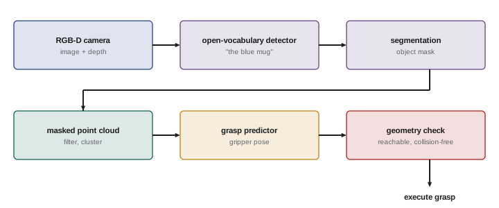
Deep networks trained on large datasets now dominate detection, segmentation and pose estimation. Vision foundation models extend this further: models trained on enormous image and image-text collections provide general-purpose features and can segment any object (promptable segmentation models) or detect objects named in free text (open-vocabulary detectors). For robots, this means a user can ask for "the blue mug with a chipped handle" without a dataset of blue mugs. Vision-language models can also describe scenes and answer questions, supporting task reasoning (Lesson 11).
Learned perception brings new failure modes: confident mistakes on unusual lighting, viewpoints or objects; sensitivity to camera changes; and occasional hallucinated detections. Robots mitigate these by combining learned detections with geometric checks (does the detected cup actually sit on a surface at a plausible height?), tracking over time rather than trusting single frames, and asking for help or retrying when confidence is low.
Synchronization and calibration
Fusing data from several sensors requires knowing exactly when each measurement was taken and where each sensor is. Time synchronization, through hardware triggers, precision time protocol (PTP) or careful timestamping, ensures that a camera image and a joint reading taken at the same moment are paired correctly; a 50 ms mismatch on a moving arm or vehicle can shift a point by centimetres. Extrinsic calibration between cameras, lidars and the robot body must be maintained, since bumps and thermal changes can shift sensors over time. Many systems monitor calibration online and flag drift.
Worked problem
Choosing sensors for a bin-picking cell
A cell must pick shiny metal brackets from a bin at 0.8 m from the sensor with ±2 mm accuracy, under factory lighting with some sunlight from skylights. Which depth sensor approach fits best?
Show solution
- Range and accuracy: 0.8 m with ±2 mm favours structured light or active stereo with a short baseline at close range.
- Sunlight: pure structured light may fail; choose an industrial structured light sensor with high-power projection and filters, or shade the cell.
- Shiny parts: reflective surfaces cause missing or wrong depth; use sensors designed for metal parts (multiple exposures, polarization) and pose estimation that tolerates gaps.
- Verification: measure accuracy on real brackets, not on a calibration target.
Answer: An industrial structured light 3D sensor designed for reflective parts, with shading from skylights, verified on real parts. Sensor choice must account for materials and lighting, not only range.
Perception for navigation
Mobile robots use perception mainly to find free space and obstacles. A 2D safety laser scanner at ankle height detects walls, shelves and legs reliably and is certified for safety functions, which is why it is standard on industrial AMRs. 3D lidar and depth cameras add obstacles above and below the scanner plane, such as table tops, forklift tines and overhanging loads, and detect drop-offs such as stairs and loading docks. Cameras with learned models classify obstacles, distinguishing people from boxes so the robot can slow down and keep a respectful distance. Perception for navigation must also handle reflective floors, glass walls, direct sunlight, and dust or rain outdoors, which confuse many sensors.
A useful design principle is redundancy across sensing modalities: if one sensor type fails in a particular condition, another should still detect the hazard. Combining a laser scanner, a depth camera and a bumper switch, for example, provides layers of protection with different failure modes.
Perception for manipulation
Grasping is the most common manipulation perception task. Analytic grasp planners use object models and contact mechanics to find stable grasps; data-driven grasp detectors predict grasp poses directly from depth images or point clouds and generalize to novel objects; and suction grasp detectors find flat, sealed surfaces for vacuum grippers, which dominate warehouse picking. In cluttered bins, the robot must also decide which object to pick first, avoid disturbing neighbours, and sometimes push objects apart to create space. Perception must run fast enough to keep picking rates high, often several picks per minute, while handling transparent packaging, deformable bags and reflective items.
Finally, perception systems should report their uncertainty and their failures. A detector that returns nothing when it is unsure, and a pose estimator that reports its confidence, allow planners to slow down, look again or ask for help instead of acting on a wrong guess.
Common mistakes
MistakeExpecting a single camera image to give depth.
InsteadUse depth sensors, multiple views or learned depth with care.
MistakeIgnoring that stereo error grows with distance squared.
InsteadMatch sensor and baseline to the working range.
MistakeTrusting learned detections without checks.
InsteadCombine with geometry, tracking and confidence thresholds.
MistakeFusing unsynchronized sensor data.
InsteadSynchronize clocks and timestamps carefully.
MistakeAssuming depth sensors handle glass and shiny metal.
InsteadTest on real materials and choose suitable sensors.
Summary and key terms
- Proprioceptive sensors include encoders, IMUs, force/torque, joint torque and tactile sensors.
- The pinhole model with intrinsics and distortion maps 3D points to pixels; depth is lost.
- Stereo depth uncertainty grows with distance squared.
- Stereo, structured light, ToF, lidar and radar trade range, accuracy and robustness.
- Perception tasks include detection, segmentation, 6D pose, grasps, mapping and tracking.
- Foundation models enable open-vocabulary perception but need geometric checks.
- Time synchronization and calibration are essential for sensor fusion.
- Proprioception
- Sensing the robot's own state.
- IMU
- Inertial measurement unit of accelerometers and gyroscopes.
- Intrinsic matrix
- Camera parameters mapping rays to pixels.
- Extrinsics
- The pose of a sensor relative to the robot.
- Disparity
- Pixel offset between stereo views.
- Time of flight
- Depth from light travel time.
- Point cloud
- A set of 3D points from a depth sensor.
- 6D pose
- Position and orientation of an object.
- Open-vocabulary detection
- Detecting objects described in free text.
- PTP
- Precision time protocol for clock synchronization.
Practice problems
Work each problem on paper first, then reveal the answer to check.
Name four proprioceptive sensors.
Show answer
Encoders, IMUs, force/torque sensors, joint torque sensors, tactile sensors.
Why does integrating IMU data drift?
Show answer
Small errors accumulate over time.
Project (0.1, 0, 2) m with f = 600, cx = 320.
Show answer
u = 600 × 0.05 + 320 = 350.
Why can a single image not give depth?
Show answer
Each pixel corresponds to a ray.
If depth doubles, how does stereo depth uncertainty change?
Show answer
It roughly quadruples.
Which depth sensor fails in sunlight?
Show answer
Structured light, typically.
What does 6D pose estimation give?
Show answer
An object's position and orientation.
What do open-vocabulary detectors enable?
Show answer
Finding objects described in free text.
How can learned detections be checked?
Show answer
Geometric plausibility, tracking over time, confidence thresholds.
Why does time synchronization matter?
Show answer
Mismatched timestamps misplace moving objects.
Lesson quiz · 5 questions
Score 60% or more to complete this lesson.
Create a free account to save your progress, take quizzes and earn a certificate.