
AERO-330 · Lesson 12 of 12 · 24 min
Fly-by-wire flight control
The Tern Block 2 keeps cables, pushrods and a yaw damper, because for a commuter of its size a mechanical system with limited-authority augmentation is lighter, cheaper and simpler to certify. The Swift 900 business jet that Dr. Kenji Watanabe's group is studying is a different case. Its swept wing and wide speed range make the handling change a great deal between approach and Mach 0.80 cruise, and Borealis Aerospace wants to offer envelope protection that stops the pilot stalling or overstressing it. That points to fly-by-wire: flight control computers between the pilot and the surfaces. Before Swift aerodynamic data exist, Kenji asks Arjun to prototype a pitch control law on the Tern's well-validated cruise model, so the law's structure can be tested and explained before it is tuned for the jet. This final lesson brings together the axes, modes, handling criteria and feedback of the whole course.
What fly-by-wire changes
In a fly-by-wire aircraft the pilot's stick is a transducer, not a lever. Its position becomes a command, a computer compares the command with sensed motion, and actuators move the surfaces to make the aircraft follow. Concorde flew with analogue electrical signalling in the 1960s; digital fly-by-wire entered military service in the 1970s and civil service with the Airbus A320 in 1988, followed by the Boeing 777 and most new airliners and business jets since. The benefits are substantial. The control law, not the airframe alone, sets the handling qualities, so they can be kept consistent across the speed and weight range. The natural static margin can be reduced, shrinking the tail and its trim drag. Protections can stop the aircraft exceeding its angle of attack, load factor, bank and speed limits. And the mechanical system's weight and its maintenance disappear. The costs are complexity, software assurance and the need for redundancy, because the aircraft depends on the computers for every manoeuvre.
Choosing what the stick commands
With a mechanical system, the stick commands an elevator angle and the aircraft's dynamics decide what follows. With fly-by-wire, the designer chooses what the stick commands. Three common choices for pitch are pitch rate, normal load factor, and a blend of the two called C* (C-star). Pitch rate command feels natural at low speed, where pilots fly attitudes. Load factor command suits high speed, where pilots fly flight paths and want a given pull to mean a given g. The C* criterion, introduced in the 1960s from studies of pilot preference, blends them with a crossover speed \(V_{co}\) at which the two terms contribute equally:
Below the crossover speed, pitch rate dominates the blend and the aircraft responds like a rate-command system; above it, load factor dominates. Crossover speeds of about 120 to 130 m/s are typical, close to many aircraft's manoeuvring speeds. The Airbus family uses a load factor demand law with pitch rate terms; other manufacturers use rate command with attitude hold. In each case, releasing the stick holds the current flight path or attitude, and the computers trim automatically, so the pilot never needs the trim wheel in normal operation.
The prototype law
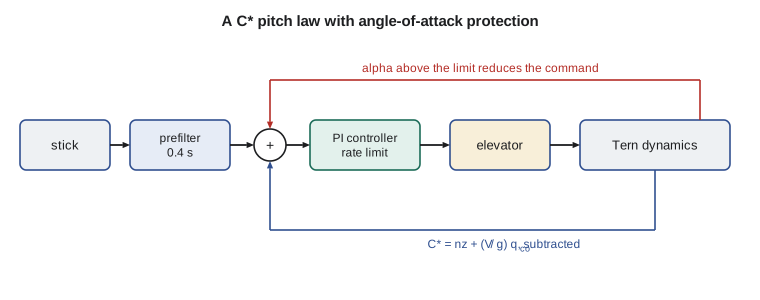
Arjun's law has four parts. A prefilter, a first-order lag of 0.4 seconds, shapes the stick command so that the response feels smooth. A proportional-integral controller drives the elevator from the C* error; the integral term makes the steady C* match the command exactly and provides the automatic trim. The elevator command is rate limited to 40 degrees per second and position limited to ±20 degrees, representing the actuators. And an angle-of-attack protection term subtracts from the command whenever the angle of attack exceeds 12 degrees from zero lift, the protection limit chosen to keep the clean wing well below its stall.
The prefilter is in the law because of a lesson learned in the first simulation run. Without it, a full stick input demanded a large elevator step that the rate limiter could not deliver, so the actuator lagged the controller, the controller pushed harder, and the elevator began to swing back and forth at about 1 Hz. This was a small-scale example of the rate-limit-induced oscillation that has caused pilot-induced oscillations in real fly-by-wire aircraft. Shaping the command so that the controller never asks for more rate than the actuator has cured it.
# A fly-by-wire pitch law for the Tern Block 2 study: the stick commands C* (a blend of
# normal load factor and pitch rate), a PI controller drives the elevator, and an angle-of-
# attack limiter protects the envelope. Short-period model in cruise, RK4 integration.
import math
m, Iyy, S, c, g, rho, u0 = 6500.0, 27000.0, 28.0, 1.73, 9.81, 0.909, 105.0
QS = 0.5 * rho * u0 ** 2 * S
CLa = 5.6
Za = -(CLa + 0.036) * QS / m                   # m/s2 per rad of alpha
Ma = -1.0 * QS * c / Iyy
Mad = -6.0 * (c / (2 * u0)) * QS * c / Iyy
Mq = -20.0 * (c / (2 * u0)) * QS * c / Iyy
Zde, Mde = -0.310 * QS / m, -1.362 * QS * c / Iyy
alpha_trim = 0.454 / CLa                       # rad from zero lift in 1 g cruise
alpha_lim = math.radians(12.0)                 # protection limit (from zero lift)
V_co = 124.0                                   # C* crossover speed, m/s
de_lim, de_rate = math.radians(20), math.radians(40)
def nz_inc(a, de): return -(Za * a + Zde * de) / g        # incremental load factor
def simulate(cstar_cmd, protect, T=8.0, dt=0.005, Kp=-0.10, Ki=-0.45, Ka=20.0):
    a = q = th = integ = de = filt = 0.0; t = 0.0; out = []
    while t < T:
        stick = cstar_cmd if t > 0.5 else 0.0
        filt += (stick - filt) * dt / 0.4                      # command prefilter, 0.4 s
        cmd = filt
        if protect and alpha_trim + a > alpha_lim:          # reduce the command near the limit
            cmd -= Ka * (alpha_trim + a - alpha_lim) * u0 / g
        cstar = nz_inc(a, de) + V_co / g * q
        err = cmd - cstar
        integ += err * dt
        de_new = Kp * err + Ki * integ
        de += max(-de_rate * dt, min(de_rate * dt, de_new - de))
        de = max(-de_lim, min(de_lim, de))
        def f(a, q):
            ad = Za / u0 * a + q + Zde / u0 * de
            qd = Ma * a + Mad * ad + Mq * q + Mde * de
            return ad, qd
        k1 = f(a, q); k2 = f(a + dt / 2 * k1[0], q + dt / 2 * k1[1])
        k3 = f(a + dt / 2 * k2[0], q + dt / 2 * k2[1]); k4 = f(a + dt * k3[0], q + dt * k3[1])
        a += dt / 6 * (k1[0] + 2 * k2[0] + 2 * k3[0] + k4[0])
        q += dt / 6 * (k1[1] + 2 * k2[1] + 2 * k3[1] + k4[1])
        t += dt; out.append((t, a, q, de))
    return out
def report(label, out):
    t, a, q, de = out[-1]
    amax = max(alpha_trim + e[1] for e in out)
    print(f"{label}: after {t:.0f} s alpha {math.degrees(alpha_trim+a):.1f} deg (peak {math.degrees(amax):.1f}),"
          f" pitch rate {math.degrees(q):.2f} deg/s, extra load factor {nz_inc(a, de):+.2f} g, elevator {math.degrees(de):+.1f} deg")
small = simulate(0.5, protect=True)
report("C* command +0.5 g, protection on ", small)
print(f"   C* reaches 90% of the command {next(t for t,a,q,de in small if nz_inc(a,de)+V_co/g*q >= 0.45) - 0.5:.2f} s after the input")
big_off = simulate(4.5, protect=False)
big_on = simulate(4.5, protect=True)
report("full aft stick (C* +4.5), protection off", big_off)
report("full aft stick (C* +4.5), protection on ", big_on)
print(f"alpha limit {math.degrees(alpha_lim):.1f} deg from zero lift, 1 g trim alpha {math.degrees(alpha_trim):.1f} deg")C* command +0.5 g, protection on : after 8 s alpha 5.8 deg (peak 5.8), pitch rate 1.23 deg/s, extra load factor +0.23 g, elevator -1.0 deg C* reaches 90% of the command 1.06 s after the input full aft stick (C* +4.5), protection off: after 8 s alpha 14.7 deg (peak 14.7), pitch rate 11.05 deg/s, extra load factor +2.06 g, elevator -8.7 deg full aft stick (C* +4.5), protection on : after 8 s alpha 12.3 deg (peak 12.3), pitch rate 8.43 deg/s, extra load factor +1.57 g, elevator -6.6 deg alpha limit 12.0 deg from zero lift, 1 g trim alpha 4.6 deg
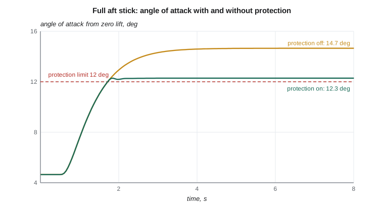
A small command of +0.5 in C* produces, after the transient, an extra load factor of 0.23 g and a pitch rate of 1.23 degrees per second, a steady pull-up, with C* reaching 90 percent of the command 1.06 seconds after the input. The steady state is exact because of the integral term, and the response has no overshoot, a quality that pilots rate highly. Full aft stick, a C* command of +4.5, would without protection take the aircraft to 14.7 degrees angle of attack and an extra 2.06 g. With protection the angle of attack levels at 12.3 degrees, the load factor at 1.57 g extra, and the pilot can hold the stick fully back without stalling. The small overshoot of the limit, 0.3 degrees, comes from the proportional form of the protection term; production laws switch to an angle-of-attack command near the limit so that the limit is held exactly.
Redundancy, software and certification
Because a fly-by-wire aircraft cannot be flown without its computers, the system must be designed so that total loss of pitch control is extremely improbable, of the order of one in a billion flight hours. Typical architectures use three or four flight control computers, sometimes of dissimilar design with separately written software, several independent sensors for each variable, actuators with multiple hydraulic or electrical power sources, and degraded modes that drop the protections but keep direct control if sensors disagree. The software is developed and verified to the highest design assurance level of the aviation software standard DO-178C, and the hardware to DO-254. Because transport category rules were written for mechanical controls, Transport Canada has issued special conditions for features such as envelope protection and electronic flight control, setting the safety objectives the design must meet. The Swift 900 would be certified against the standards for transport category aeroplanes in Chapter 525 of the Transport Canada Airworthiness Manual, with such special conditions added.
Handling-qualities criteria also change. Classic modal criteria assume a conventional aircraft; a highly augmented aircraft can have dynamics of higher order, with time delays from computation and filtering. Criteria developed for these aircraft, such as limits on equivalent time delay of about 0.1 seconds for level 1 and bandwidth-phase delay criteria, guard against the delays that cause pilot-induced oscillations. Sam will fly the prototype law in the simulator with the time delay deliberately increased to find where his ratings start to fall, a standard part of any fly-by-wire programme.
Looking back over the course
The prototype law draws on every lesson. The axes of Lesson 1 define the sensed variables. Static stability and the neutral point of Lessons 2 and 3 decide how much the law must stabilize. Elevator power from Lesson 4 sets how hard it can pull. The modes of Lessons 6 to 8 are what the law reshapes, and the criteria of Lesson 9 judge the result. Lessons 10 and 11 supplied the feedback ideas, rate damping, integral action and nested loops, from which every control law is built. Flight mechanics remains, at heart, Newton's laws applied carefully in the right axes; the art lies in turning them into an aircraft that pilots trust.
Worked problem
C* at the crossover speed
With \(V_{co} = 124\) m/s, an aircraft pulls up with an extra load factor of 0.5 g and a pitch rate of 0.03 rad/s. Find C* and the share contributed by pitch rate.
Show solution
- Pitch rate term: \(124/9.81 \times 0.03 = 0.379\).
- \(C^* = 0.5 + 0.379 = 0.879\); pitch rate supplies 43 percent.
Answer: In a steady pull-up at speed V, \(n_z = Vq/g\), so the two terms are equal when V equals the crossover speed.
Worked problem
Steady pull-up from a C* command
At 105 m/s in a steady pull-up, extra load factor and pitch rate are linked by \(\Delta n = u_0 q/g\). For a C* command of 0.5 with \(V_{co} = 124\) m/s, find the steady extra load factor.
Show solution
- \(C^* = \Delta n + (V_{co}/u_0)\Delta n = \Delta n(1 + 124/105) = 2.18\,\Delta n\).
- \(\Delta n = 0.5/2.18 = 0.23\) g, and \(q = 0.23 \times 9.81/105 = 0.0215\) rad/s, or 1.23 degrees per second.
Answer: These match the program's steady values exactly, a useful check on both the law and the simulation.
Common mistakes
MistakeAssuming fly-by-wire removes the need to understand the aircraft's natural dynamics.
InsteadThe law is designed around those dynamics and must handle failures that remove it.
MistakeIgnoring actuator rate limits in control law design.
InsteadRate saturation adds lag and can cause oscillations; shape commands accordingly.
MistakeTreating envelope protection as a stall warning.
InsteadProtection limits the command so the limit is not exceeded at all.
MistakeOverlooking computational time delay.
InsteadDelays of a tenth of a second can degrade handling; criteria limit them.
Summary and key terms
- Fly-by-wire places computers between the pilot and the surfaces, so the control law sets the handling qualities.
- Pitch laws command pitch rate, load factor or the C* blend; integral action provides exact steady response and automatic trim.
- Envelope protection limits commands to keep angle of attack, load factor and other variables within limits.
- Actuator rate limits and time delays must be respected to avoid oscillations.
- Redundant computers and sensors, high software assurance and special conditions make the system certifiable.
- The prototype law holds the Tern model at a 12 degree angle-of-attack limit under full aft stick.
- Fly-by-wire
- A flight control system in which pilot commands are transmitted electrically to computers that drive the surfaces.
- C*
- A blend of normal load factor and pitch rate used as a pitch command variable.
- Crossover speed
- The speed at which the load factor and pitch rate terms of C* are equal in a steady pull-up.
- Envelope protection
- Control law features that prevent the aircraft exceeding its limits.
- Prefilter
- A filter shaping the pilot command before it reaches the feedback loop.
- Special condition
- Additional certification requirements issued for novel design features.
- Equivalent time delay
- A measure of lag in a highly augmented aircraft response.
Practice problems
Work each problem on paper first, then reveal the answer to check.
Name two benefits of fly-by-wire.
Show answer
Consistent handling through the control law and envelope protection (also relaxed stability and weight savings).
What does the integral term provide in the C* law?
Show answer
Exact steady response and automatic trim.
Why was the prefilter added?
Show answer
To avoid a rate-limit-induced elevator oscillation for large inputs.
In the program, what angle of attack is reached with protection off?
Show answer
About 14.7 degrees.
Below the crossover speed, which C* term dominates?
Show answer
The pitch rate term.
Why are flight control computers made redundant and dissimilar?
Show answer
Loss of control must be extremely improbable, including from common software errors.
Lesson quiz · 5 questions
Score 60% or more to complete this lesson.
Create a free account to save your progress, take quizzes and earn a certificate.