
AERO-330 · Lesson 1 of 12 · 25 min
Axes and equations of motion
Two years of wind tunnel work and structural analysis have given the Tern Block 2 a new wing, a lighter wing box and a slightly longer fuselage. Now the question changes from 'will it lift and will it hold together?' to 'will it fly the way pilots expect?' At Borealis Aerospace in Winnipeg, that question belongs to the flight sciences group. Tomasz Wierzbicki, head of aerodynamics, has set up a stability and control study for Block 2 and asked Arjun Mehta to build the flight dynamics model from first principles. Sam Littlechild, the company test pilot, will fly the result in the engineering simulator and, later, in the aircraft itself. Hélène Lavoie, the flight controls lead, will design the yaw damper and autopilot on top of it. This course follows that study from the axes it is written in to the fly-by-wire law Dr. Kenji Watanabe is sketching for the Swift 900 jet.
Flight mechanics is the study of how an aircraft moves as a rigid body under aerodynamic, propulsive and gravity forces. Stability asks whether it returns to its trimmed state after a disturbance; control asks how the pilot or an automatic system moves it to a new one. Everything rests on a careful choice of axes and a careful statement of Newton's laws in those axes, and that is the subject of this first lesson.
Why the choice of axes matters
Newton's second law holds in an inertial frame. For an aircraft flying for minutes rather than hours, a frame fixed to the flat Earth is close enough: the Earth's rotation and curvature matter for navigation and for very long flights, not for the stability of a commuter aeroplane. The aircraft's forces, however, are most naturally written in a frame fixed to the aircraft, because the aerodynamic coefficients from the wind tunnel and the moments of inertia from the mass properties are measured that way. The equations of motion must therefore connect two kinds of axes: Earth axes, in which gravity is simple and the flight path is drawn, and body axes, in which the forces and inertias are simple.
In Earth axes the usual convention in flight mechanics is north, east and down, so that height is negative along the third axis and a positive pitch angle points the nose up. In body axes, \(x\) points forward along a reference line in the fuselage, \(y\) points out of the right wing, and \(z\) points down through the floor, completing a right-handed set. Velocities along these axes are \(u, v, w\); angular rates about them are roll rate \(p\), pitch rate \(q\) and yaw rate \(r\); and the aerodynamic moments are rolling moment \(L\), pitching moment \(M\) and yawing moment \(N\). The positive directions follow the right-hand rule: a positive roll rate lowers the right wing, a positive pitch rate raises the nose and a positive yaw rate swings the nose to the right.
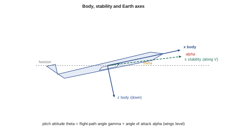
Body, stability and wind axes
Two variants of body axes appear constantly. Stability axes are still fixed to the aircraft, but their \(x\) axis is aligned with the velocity in the steady reference flight condition, so that in that condition \(w\) is zero. Linearized stability analysis is usually done in stability axes because the steady state is then especially simple. Wind axes go one step further and stay aligned with the instantaneous velocity, so they rotate relative to the aircraft as the angle of attack and sideslip change. Lift and drag are defined in wind axes: lift perpendicular to the velocity, drag along it. Converting the wind tunnel's lift and drag into body-axis forces is one of the first jobs in any flight model.
The angles linking body axes to the velocity are the angle of attack \(\alpha\) and the sideslip angle \(\beta\). With the body-axis velocity components known,
Positive sideslip means the relative wind comes from the right of the nose, which is what happens when the nose yaws left of the flight path. Sideslip is small in normal flight but central to the lateral-directional behaviour of Lessons 5 and 8.
Euler angles and the rotation matrix
The orientation of the body axes relative to Earth axes is described by three Euler angles applied in a fixed order. The aeronautical convention is the 3-2-1 sequence: first rotate by the heading or yaw angle \(\psi\) about the Earth's down axis, then by the pitch angle \(\theta\) about the new \(y\) axis, then by the bank angle \(\phi\) about the final \(x\) axis. The order matters, because finite rotations do not commute: the same three numbers applied in another order give a different attitude. The combined rotation is a 3 × 3 orthogonal matrix, whose transpose is its inverse, so converting a vector from body to Earth axes and back is a simple matrix product.
The angular rates measured by the gyros are body-axis rates, not Euler angle rates. They are related by the kinematic equations
The \(\tan\theta\) and \(1/\cos\theta\) terms blow up at a pitch attitude of 90 degrees. This is gimbal lock: at vertical attitude, yaw and roll become the same rotation and the Euler angles are no longer unique. A commuter aircraft never gets there, but simulators and flight control computers that must handle any attitude use quaternions, four parameters with no singularity, and convert to Euler angles only for display.
Newton's laws in rotating axes
Because body axes rotate with the aircraft, the rate of change of a vector seen in body axes differs from its rate of change in the inertial frame. For the velocity, the inertial acceleration is the body-axis rate of change plus the cross product of the angular velocity with the velocity. Writing the forces per unit mass as \(X, Y, Z\) and including gravity gives the force equations
The moment equations come from the rate of change of angular momentum. For an aircraft symmetric about its \(xz\) plane, the products of inertia \(I_{xy}\) and \(I_{yz}\) vanish and only \(I_{xz}\) remains.
Together with the three kinematic equations for the Euler angles and three navigation equations for position, these make twelve first-order differential equations: the full six-degree-of-freedom model. They are nonlinear, mainly through the products of rates and the trigonometric gravity terms. Simulators integrate them directly. Stability analysis linearizes them about a steady flight condition, which Lesson 6 does, and the result splits neatly into longitudinal and lateral-directional sets.
Several assumptions are hidden in these equations and are worth stating. The aircraft is rigid, so wing bending and fuselage flexibility are ignored; Block 2's first wing bending frequency is far above the rigid-body modes, so this is acceptable, though Marcus Webb's structures group checks it. The mass is constant over the manoeuvre; for a hybrid-electric aircraft whose batteries do not lose mass, this holds even better than for a fuel-burning one. The Earth is flat and not rotating. And the engines' spinning parts produce no gyroscopic moments, which is a reasonable approximation for turboprops whose propellers turn in opposite directions.
# Axes and Euler angles for the Tern Block 2: build the body-to-Earth rotation, then recover
# angle of attack, sideslip and flight path from the body-axis velocity.
import math
d2r, r2d = math.pi / 180, 180 / math.pi

def dcm(phi, theta, psi):
    """Rotation matrix from body axes to Earth (north-east-down) axes, 3-2-1 sequence."""
    cf, sf = math.cos(phi), math.sin(phi)
    ct, st = math.cos(theta), math.sin(theta)
    cp, sp = math.cos(psi), math.sin(psi)
    return [[ct * cp, sf * st * cp - cf * sp, cf * st * cp + sf * sp],
            [ct * sp, sf * st * sp + cf * cp, cf * st * sp - sf * cp],
            [-st, sf * ct, cf * ct]]

def mul(M, v): return [sum(M[i][j] * v[j] for j in range(3)) for i in range(3)]
def tr(M): return [[M[j][i] for j in range(3)] for i in range(3)]

# A gentle climbing turn: 20 deg bank, 5 deg pitch, heading 045
phi, theta, psi = 20 * d2r, 5 * d2r, 45 * d2r
R = dcm(phi, theta, psi)
# check orthogonality: R times its transpose should be the identity
RRt = [[sum(R[i][k] * R[j][k] for k in range(3)) for j in range(3)] for i in range(3)]
err = max(abs(RRt[i][j] - (1 if i == j else 0)) for i in range(3) for j in range(3))
print(f"orthogonality error {err:.1e}")

# body-axis velocity measured by the air data system (still air): u forward, v right, w down
u, v, w = 104.6, 1.8, 6.4                  # m/s
V = math.sqrt(u * u + v * v + w * w)
alpha = math.atan2(w, u); beta = math.asin(v / V)
print(f"airspeed {V:.1f} m/s, alpha {alpha*r2d:.2f} deg, beta {beta*r2d:.2f} deg")

# velocity in Earth axes, then flight-path angle and track
vn, ve, vd = mul(R, [u, v, w])
gamma = -math.asin(vd / V); track = math.atan2(ve, vn)
print(f"Earth velocity N {vn:.1f}, E {ve:.1f}, D {vd:.1f} m/s")
print(f"flight-path angle {gamma*r2d:.2f} deg, track {track*r2d:.1f} deg")
print(f"check: theta - alpha (wings level would give gamma) = {(theta-alpha)*r2d:.2f} deg")

# gravity seen in body axes (what the accelerometers must cancel in steady flight)
gb = mul(tr(R), [0, 0, 9.81])
print("gravity in body axes  x {:.2f}  y {:.2f}  z {:.2f} m/s2".format(*gb))
print(f"load factor for a level turn at this bank: n = 1/cos(phi) = {1/math.cos(phi):.3f}")orthogonality error 2.2e-16 airspeed 104.8 m/s, alpha 3.50 deg, beta 0.98 deg Earth velocity N 74.4, E 73.7, D -2.5 m/s flight-path angle 1.37 deg, track 44.7 deg check: theta - alpha (wings level would give gamma) = 1.50 deg gravity in body axes x -0.85 y 3.34 z 9.18 m/s2 load factor for a level turn at this bank: n = 1/cos(phi) = 1.064
The program reproduces what the air data and inertial systems do on every flight. From the measured body velocities it finds an airspeed of 104.8 m/s , an angle of attack of 3.5 degrees and almost one degree of sideslip. Rotating the velocity into Earth axes gives a climb at a flight-path angle of 1.37 degrees on a track of 44.7 degrees. In wings-level flight the flight-path angle would simply be pitch attitude minus angle of attack, 1.5 degrees; the bank and sideslip make the true value slightly different, which is why the simple formula is only taught for wings-level flight. The gravity components show that in a 20 degree bank the accelerometers see a sideways component of 3.34 m/s², which in a coordinated turn is balanced by the aircraft's own sideforce and felt by passengers as a push into the seat, not toward the window.
| Quantity | Symbol | Positive direction |
|---|---|---|
| Forward, side, down velocity | u, v, w | along +x, +y (right), +z (down) |
| Roll, pitch, yaw rate | p, q, r | right wing down, nose up, nose right |
| Rolling, pitching, yawing moment | L, M, N | same senses as p, q, r |
| Bank, pitch, heading angle | φ, θ, ψ | right wing down, nose up, clockwise from north |
| Angle of attack, sideslip | α, β | nose above velocity, wind from the right |
Worked problem
Angle of attack and sideslip from body velocities
A flight test data point gives \(u = 82\) m/s, \(v = -3\) m/s and \(w = 9\) m/s. Find the airspeed, angle of attack and sideslip.
Show solution
- \(V = \sqrt{82^2 + 3^2 + 9^2} = \sqrt{6814} = 82.5\) m/s.
- \(\alpha = \tan^{-1}(9/82) = 6.26\) degrees.
- \(\beta = \sin^{-1}(-3/82.5) = -2.08\) degrees.
Answer: The negative sideslip means the relative wind comes from the left; the nose is yawed slightly right of the flight path.
Worked problem
Rates in a steady turn
The Tern flies a steady level turn at 25 degrees of bank and 90 m/s. Find the turn rate and the body-axis rates \(q\) and \(r\) (take \(\theta \approx 0\)).
Show solution
- Turn rate \(\dot\psi = g\tan\phi/V = 9.81 \times 0.466/90 = 0.0508\) rad/s, or 2.91 degrees per second.
- From the kinematic equations with \(\theta = 0\): \(q = \dot\psi\sin\phi = 0.0215\) rad/s, \(r = \dot\psi\cos\phi = 0.0460\) rad/s.
Answer: A level turn is not a pure yaw. Part of the turn rate appears as pitch rate in body axes, which is why the pilot holds back pressure on the control column throughout a turn.
Common mistakes
MistakeMixing body-axis rates with Euler angle rates.
InsteadGyros measure p, q, r; Euler rates follow from the kinematic equations, and they are equal only in special cases.
MistakeApplying the three Euler rotations in a different order.
InsteadThe aeronautical sequence is yaw, then pitch, then roll; another order gives a different attitude.
MistakeForgetting the cross-product terms when writing Newton's law in body axes.
InsteadBody axes rotate, so qw − rv and similar terms appear in the force equations.
MistakeTreating flight-path angle as θ − α in a banked turn.
InsteadThat relation holds only for wings-level flight without sideslip.
Summary and key terms
- Flight dynamics uses Earth axes for gravity and the flight path, and body axes for forces, moments and inertias.
- Stability axes are body axes aligned with the reference velocity; wind axes follow the instantaneous velocity and define lift and drag.
- Angle of attack and sideslip relate body axes to the velocity.
- Orientation is described by 3-2-1 Euler angles and an orthogonal rotation matrix, with a singularity at 90 degrees of pitch.
- Newton's laws in rotating body axes give six nonlinear equations of motion which, with kinematics and navigation, make the twelve-state rigid-body model.
- Body axes
- Axes fixed to the aircraft: x forward, y right, z down.
- Stability axes
- Body-fixed axes with x along the velocity in the reference flight condition.
- Wind axes
- Axes aligned with the instantaneous velocity, in which lift and drag are defined.
- Euler angles
- Yaw, pitch and bank angles describing attitude by three successive rotations.
- Gimbal lock
- The singularity of Euler angles at 90 degrees of pitch.
- Sideslip
- The angle between the velocity and the aircraft plane of symmetry.
- Six degrees of freedom
- Three translations and three rotations of a rigid body.
Practice problems
Work each problem on paper first, then reveal the answer to check.
Give the body-axis directions used in flight mechanics.
Show answer
x forward, y out the right wing, z down.
Why are stability axes used for linear stability analysis?
Show answer
Because in the reference condition w is zero, which simplifies the steady state.
What is gimbal lock?
Show answer
At 90 degrees of pitch, yaw and roll rotations coincide and the Euler angles become singular.
In the program, set the bank angle to zero. What is the flight-path angle now?
Show answer
Close to θ − α, as expected for wings-level flight.
Which product of inertia remains for an aircraft symmetric about its xz plane?
Show answer
I_xz.
Name two assumptions in the rigid-body equations.
Show answer
A rigid aircraft and constant mass (also flat, non-rotating Earth).
Lesson quiz · 5 questions
Score 60% or more to complete this lesson.
Create a free account to save your progress, take quizzes and earn a certificate.