
SMW-310 · Lesson 3 of 12 · 19 min
Site layout and elevations
Layout is the step that decides whether everything else goes smoothly. If the hanger points are in the right places and the elevations are right, the duct goes up straight, the joints meet, the branches line up with the diffusers and the other trades find the space they were promised. If the layout is wrong, every later step is a fight. This lesson covers how a duct crew finds its reference points on site, transfers them to the ceiling, sets elevations with lasers and checks its own work.
On the Ashgrove retrofit, Aggie MacLeod did most of the layout and taught it to Kai over the first two weeks of the summer. Her rule was to measure from the building's own references, never from something another trade installed, because a reference used by everyone keeps everyone's work in the same place.
Reference lines and benchmarks
Every building has a set of reference lines and levels that all trades work from. In plan, the references are the structural gridlines, the lettered and numbered lines through the columns that appear on every drawing. On a new building the surveyor marks the gridlines or offset lines on each floor slab, usually a meter or a few feet off the true line so the marks are not covered by walls. In height, the reference is a benchmark: a mark of known elevation, often the finished floor level of each story or a line snapped on the columns a fixed distance above it.
Drawings give elevations either above the finished floor or as absolute elevations tied to the site datum. On Ashgrove the library floor was the reference: the drawings gave the bottom of the duct as a height above the finished floor, and the general contractor had snapped a line on every column 3 ft 3 3/8 in above the floor. On the Eastgate addition, the drawings used absolute elevations, with the main floor at an elevation in the hundreds of meters or feet, so Lin's shop drawings converted each bottom-of-duct elevation to a height above the local floor for the crew.
In an old building there may be no gridlines left, and floors are rarely level. Aggie re-established Ashgrove's references from the column centers shown on the original structural drawings, checked the floor with the laser and found it fell about 3/4 in from one end of the library to the other. She decided to run the duct level and to take up the difference in the hanger rods, because a duct that follows a sagging floor looks wrong, makes the joints harder and can trap condensation in cold climates.
Transferring layout from floor to ceiling
Hanger points are laid out on the floor, where measuring is easy, and then transferred straight up to the structure. A plumb bob does the job but is slow; a plumb-point laser, also called a dot laser or point laser, projects a dot straight up from a mark on the floor to the deck or beam above. The installer marks the dot on the structure, then installs the insert, anchor or beam clamp there.
Laying out on the floor follows a simple routine. Snap a chalk line on the floor along the duct's centerline, measured from the gridlines or offset lines. Mark the hanger points along the line at the spacing on the shop drawing, adjusted to miss joints, branches, dampers and the other trades' sleeves. Mark the branches and the terminal positions, checked against the reflected ceiling plan. Then transfer each point up. On a long run, check the line at both ends against the gridlines before marking anything in between: a small angle error at one end becomes a large offset at the other.
On large new buildings, many contractors now lay out with a robotic total station driven from the coordinated model, which shoots each hanger point directly from building control points without chalk lines. The principle is the same: every point is located from the building's references, not from the last point.
Setting elevations with a laser
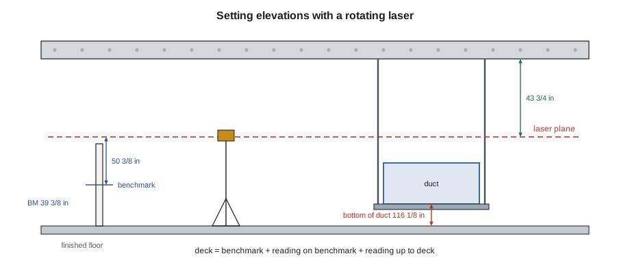
A rotating laser level spins a beam around a level plane. With a detector on a rod, or with a target on the ceiling, the installer can read the distance between the laser plane and any point. The method is the same as differential leveling in surveying: set the laser, take a reading on the benchmark to find the height of the laser plane, then take readings at other points and subtract.
Line lasers project horizontal and vertical lines on walls and are handy for short runs and for squaring branches. Green lasers are easier to see than red in daylight. Whatever the tool, the installer checks it: a laser that is out of calibration by a small angle can put a far wall off by more than the joint tolerance. Aggie checked hers each Monday by a two-peg check, comparing readings between two marks from both ends of the room, the same idea used to check surveying levels.
From elevations to rod lengths
Once the elevation of the underside of the structure is known at each hanger point, the rod or strap length follows from the bottom-of-duct elevation, the duct depth, the trapeze or strap detail and the insulation. Doing the arithmetic before going up the lift saves trips and stops the crew cutting rods on the platform, where offcuts fall on people.
At the library, Aggie read the laser on the benchmark and at each hanger point on the deck above trunk T1, then had Kai work out the rod lengths. The duct hung on angle trapezes, with the rod carrying the trapeze; the cut length includes the threaded length that passes through the trapeze and nuts.
# Rod lengths from laser readings (all in in)
benchmark = 39.375       # benchmark height above finished floor
rod_on_bm = 50.375       # laser plane reading on the rod standing on the benchmark
laser = benchmark + rod_on_bm
print(f"laser plane at {laser:.2f} in above the floor")
up_to_deck = [43.125, 43.375, 43.625, 43.875, 44.0625]      # measured from the laser plane up to the deck at each hanger point
bod = 116.125            # bottom of duct above the floor, from the shop drawing
insul = 1          # wrap under the duct
trapeze = 1.5        # angle depth
tail = 2          # rod passing below the trapeze for nuts and washers
for k, up in enumerate(up_to_deck, 1):
    deck = laser + up
    rod = deck - (bod - insul - trapeze) + tail
print(f"hanger {k}: deck {deck:.2f}, rod length {rod:.2f} in")laser plane at 89.75 in above the floor hanger 1: deck 132.88, rod length 21.25 in hanger 2: deck 133.12, rod length 21.50 in hanger 3: deck 133.38, rod length 21.75 in hanger 4: deck 133.62, rod length 22.00 in hanger 5: deck 133.81, rod length 22.19 in
The deck rose slightly along the run, so the rods got longer toward the far end even though the duct was dead level. Kai cut the rods on the floor with a rod shear, labeled each with its hanger number, and Aggie checked the first and last against the laser after hanging.
Slope, tolerance and how straight is straight
Most supply and return duct is run level. Some duct is sloped on purpose: outside air intakes and exhaust duct that can collect condensation or rain are often sloped back toward a drain or louver, and kitchen grease duct has a minimum slope set by code, which SMW-410 covers. A slope is given as a ratio or a percentage, such as 1/8 in per foot, and is set with the laser by changing the bottom-of-duct elevation along the run.
Specifications rarely give a tolerance for straightness, but good practice and the trades around the duct demand one. Keelson's field standard is to set duct within a few millimeters or an eighth of an inch of its elevation at each hanger and to keep runs straight by eye along their length. Joints should meet without forcing. A duct that has to be pulled into line with a come-along at a joint is a sign of a layout error, and forcing it puts stress into the joint, the hangers and the sealant.
Common layout problems and how to catch them
Most layout errors come from a few sources: measuring from the wrong reference, accumulating small errors by measuring point to point, reading the laser wrong, or confusing the elevation reference. Aggie's checks were simple. Measure every point from the gridline, not from the last point. Check the run end to end against the drawing dimensions before transferring anything. Read the laser twice. Write down whether each elevation is bottom of duct, centerline or top. And when a number looks odd, stop and find out why.
In the Ashgrove library, the check caught a mistake on the second day. The return grille positions Kai had marked from the mechanical plan were half a ceiling tile off the reflected ceiling plan. The architect's grid had been shifted to center the lights after the mechanical drawings were issued, so the diffuser and grille positions followed the grid. Moving the marks on the floor took ten minutes; moving installed branches would have taken a day.
Worked problem
Elevation from a laser reading
The benchmark is 39 3/8 in above the floor. The laser reads 50 3/8 in on the rod standing on the benchmark. At a hanger point the target reads 43 3/4 in from the laser plane up to the deck. The bottom of duct is 116 1/8 in, the duct sits on a 1 1/2 in angle trapeze with 1 in of wrap underneath, and 2 in of rod is left below the trapeze. What rod length?
Show solution
- Laser plane = 39.375 + 50.375 = 89.75 in above the floor.
- Deck = 89.75 + 43.75 = 133.5 in.
- Top of trapeze angle = 116.125 − 1 − 1.5 = 113.625 in.
- Rod = 133.5 − 113.625 + 2 = 21.875 in.
Answer: Cut the rod to 21 7/8 in and label it with the hanger number.
Layout on a busy floor
Layout marks on a construction floor do not last. Other trades walk on them, scissor lifts drive over them, and drywall dust covers them. Aggie used a few habits to keep her layout useful. She snapped chalk lines with colored chalk that the general contractor had assigned to the duct trade, so nobody confused them with plumbing or electrical marks. She marked hanger points with a small cross and the hanger number in paint marker, not just a dot, so a mark could be identified after it was partly rubbed out. She transferred points to the structure on the same day she marked them, before the floor got busy, and she photographed the marked floor of each bay with a tape in the picture, so a lost mark could be found again.
On the deck, the transferred marks were circled and tagged with the hanger number and the trade, because the sprinkler and electrical crews were marking the same deck. When two trades' points landed within a few inches of each other, Aggie talked to the other foreman before anyone drilled, because two anchors that close share the same concrete and both lose capacity, as lesson 5 explains. Layout is also where the crew checks that the duct route clears the light fixtures, sprinkler heads and access panels shown on the reflected ceiling plan, while there is still time to adjust the route on paper.
Finally, Aggie checked her own work. Before transferring anything, she measured the total length of each run on the floor against the shop drawing and the diagonal of each rectangular area against its calculated value, a quick test for a layout that is out of square.
Common mistakes
MistakeMeasuring each hanger point from the last one.
InsteadMeasure every point from the gridline or offset line so errors do not add up.
MistakeUsing another trade's pipe or tray as a reference.
InsteadWork from the building's gridlines and benchmarks.
MistakeFollowing a sagging floor or deck with the duct.
InsteadRun duct level, or at the specified slope, and take up the difference in the rods.
MistakeCutting rods on the lift.
InsteadWork out lengths first and cut them on the floor.
MistakeNever checking the laser.
InsteadDo a regular two-peg check and recheck after a drop.
Summary and key terms
- Layout in plan works from the structural gridlines; layout in height works from a benchmark.
- Points are marked on the floor and transferred up with a plumb-point laser.
- A rotating laser gives a level plane: plane height = benchmark + reading on the benchmark.
- Rod lengths come from deck elevation, bottom of duct, trapeze, insulation and the tail below the nut.
- Duct is run level or at a specified slope; joints should meet without forcing.
- Check the run against the reflected ceiling plan before installing branches.
- Gridline
- A reference line through the building columns, shown on every drawing.
- Benchmark
- A mark of known elevation used as the reference for heights.
- Plumb-point laser
- A laser that projects a dot straight up or down to transfer a point.
- Rotating laser level
- A laser that sweeps a level plane around a room.
- Two-peg check
- A test of a level or laser by comparing readings between two marks from both ends.
- Offset line
- A line marked a fixed distance from a gridline so it stays visible.
Practice problems
Work each problem on paper first, then reveal the answer to check.
The laser plane is 90 in above the floor and the deck reads 41 1/2 in above the plane. The bottom of duct is 114 in with 1 in wrap and a 1 1/2 in trapeze; leave 2 in of tail. What rod length?
Show answer
Deck 131.5; top of trapeze 114 − 2.5 = 111.5; rod 131.5 − 111.5 + 2 = 22 in.
A duct must slope 1/8 in per foot over a 40 ft run. How much lower is the far end?
Show answer
40 × 1/8 = 5 in.
Why are hanger points measured from the gridline rather than from each other?
Show answer
So small errors do not accumulate along the run.
What tool transfers a floor mark straight up to the deck?
Show answer
A plumb-point laser or a plumb bob.
Lesson quiz · 5 questions
Score 60% or more to complete this lesson.
Create a free account to save your progress, take quizzes and earn a certificate.