
SMW-310 · Lesson 10 of 12 · 19 min
Equipment and terminal connections
Duct starts and ends at equipment. Air handlers, rooftop units, fans, coils and filters push air into the system; terminal units such as variable air volume boxes control it; diffusers, registers and grilles deliver it to the rooms and take it back. Every one of those connections affects how the system performs. A badly made fan connection can cost a large share of the fan's pressure before the air has gone anywhere, a crushed flexible duct can starve a diffuser, and a rigid connection to a vibrating fan sends noise down the duct into every room. This lesson covers how the crew makes those connections and what makes them good.
The Ashgrove retrofit gave Kai examples of most of them: a new rooftop unit feeding the library and corridor mains through a curb, a few small exhaust fans, variable air volume boxes for the administration wing, ceiling diffusers and return grilles, and flexible duct to the library diffusers where the specification allowed it.
Flexible connectors at fans and air handlers
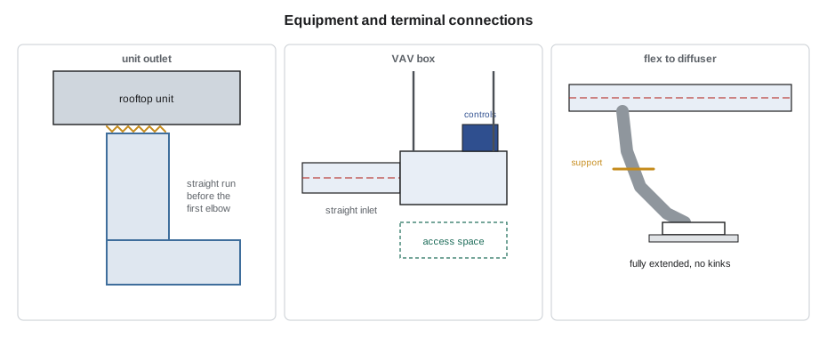
Fans and air handlers vibrate, and they move slightly when they start and stop. A flexible connector, a short collar of coated fabric between two metal strips, isolates that movement and vibration from the duct. Flexible connectors are installed with a little slack, so they are neither stretched tight nor squashed, and with the duct and the equipment opening aligned. They are not for taking up misalignment: a connector pulled sideways to meet a duct that is off by a few centimeters or an inch transmits vibration, wears quickly and leaks.
Flexible connector fabric must meet the flame and smoke rules for duct materials, and connectors on outdoor or high-temperature equipment need fabric rated for the conditions. The duct beyond the connector must have its own supports; the equipment must never carry it.
Fan and air handler connections
The way air enters and leaves a fan changes how much air it delivers. Fans are rated in test conditions with straight, uniform flow at the inlet and outlet. An elbow right at the inlet makes the air spin and enter unevenly; an abrupt fitting at the outlet throws away pressure. The loss is called system effect, and it is one of the most common reasons a new system does not reach its design airflow. Good practice is a straight run of duct at the fan outlet of a few duct diameters before the first elbow or branch, and smooth, gradual transitions at inlets and outlets. Where space does not allow it, the engineer may accept turning vanes or other fittings, but the crew does not improvise.
The Ashgrove rooftop unit sat on a roof curb over a new opening in the roof deck. Its supply and return connected down through the curb into short plenums, then turned into the corridor and library mains. Sean's crew installed the curb adapter and the drops before the crane day, so the unit could be set and connected in one shift, and they kept the drop below the supply outlet straight for well over four feet before the first elbow, as the engineer's detail required.
Variable air volume boxes and other terminals
A variable air volume box, or VAV box, is a damper with a flow sensor and a controller, sometimes with a reheat coil, that varies the air to a zone. The box measures airflow with a sensor at its inlet, and the reading is only accurate if the air arrives straight and evenly. Manufacturers call for a straight inlet duct of several inlet diameters before the box; an elbow or a flexible duct right at the inlet can make the box read wrong and control badly. Boxes are hung from their own supports, not from the duct, and need clear access to the controller and the reheat coil valve for the controls technician and maintenance staff.
The sheet metal crew sets and connects the box; the controls contractor wires it, and the pipefitter connects any hot water reheat coil. Those trades need the box in the right place, at the right orientation and with the access side clear, so the crew checks the shop drawing for the access side before hanging it. At Ashgrove's administration wing, one box drawn with its controls on the wall side was turned around on the floor before it was lifted, saving a day of rework for the controls contractor.
Diffusers, registers and grilles
Air terminals in a lay-in ceiling sit in the grid, and the branch duct connects to their neck, either directly with a rigid duct or through a short flexible duct. In hard ceilings they are fastened to a frame or to the duct. The crew sets terminals to the reflected ceiling plan, square to the grid, and checks each diffuser's pattern: a four-way diffuser blowing into a wall, or a one-way slot pointing the wrong way, upsets the room's air distribution. Diffusers with adjustable patterns are set as the schedule shows, and the balancer fine-tunes them later.
Return and exhaust grilles may connect to duct or open into a ceiling plenum. Where the ceiling space is used as a return plenum, everything in it must meet the plenum's material and wiring rules, and the crew must not leave openings where return air could short-circuit. Transfer ducts and grilles through walls let air pass between rooms; through rated walls, they need dampers like any other penetration.
Flexible duct
Flexible duct, a wire helix covered with a film and usually wrapped with insulation and a jacket, is quick to install and absorbs small misalignments at diffusers. It also has much more friction than rigid duct, and much more again when it is compressed, sagged or bent sharply. Specifications commonly limit flexible duct to short final connections, often to a maximum length such as 5 ft, require it to be listed as a Class 1 air duct, and require it to be fully extended, supported at intervals with wide straps or saddles, and bent no tighter than about one duct diameter at the centerline.
Flexible duct is connected to a collar with the inner core pulled over the collar and fastened with a clamp or tie, sealed with mastic or listed tape, and then the insulation and jacket are pulled over and fastened separately. A connection that captures only the jacket leaks through the core. Sagging and compressed flex is one of the most common causes of starved diffusers in buildings.
Kai checked how much a compressed flexible connection would cost the library diffusers, using illustrative correction factors for compression of the kind manufacturers and industry guides publish.
# Pressure loss in a flexible duct connection vs compression (illustrative factors)
length = 4                # installed length, ft
rigid_loss = 0.0015           # friction loss of the same size rigid round duct, in w.g. per ft
stretched = 1.6             # fully extended flex compared with rigid round
factors = [(0, 1.0), (10, 1.5), (20, 2.5), (30, 4.0)]   # percent compressed, multiplier on stretched flex
for pct, k in factors:
    loss = length * rigid_loss * stretched * k
    print(f"{pct:>2} percent compressed: about {loss:.4f} in w.g.")
budget = 0.015              # pressure the branch design allowed for the final connection, in w.g.
ok = [pct for pct, k in factors if length * rigid_loss * stretched * k <= budget]
print(f"within the design allowance of {budget} in w.g. up to {max(ok)} percent compression")0 percent compressed: about 0.0096 in w.g. 10 percent compressed: about 0.0144 in w.g. 20 percent compressed: about 0.0240 in w.g. 30 percent compressed: about 0.0384 in w.g. within the design allowance of 0.015 in w.g. up to 10 percent compression
A neatly extended short connection used about half of its pressure allowance. The same flex pushed together by a fifth of its length, which happens easily when an installer leaves extra length to avoid cutting it, used more than its allowance, and the diffuser at the end of it would come up short at balancing.
Outside air, louvers and exhaust terminations
Outside air intakes and exhaust outlets connect to louvers in walls or hoods and caps on roofs. The louver's free area, not its face size, decides its velocity and how much rain it lets through. The duct or plenum behind an intake louver is sealed watertight, sloped or drained so any rain that enters runs back out, and insulated where it carries cold air through heated space. Intake and exhaust openings must be kept apart by the distances the code and specification require, so exhaust air is not drawn back in; at Ashgrove, the new rooftop unit's outside air hood faced away from the kitchen exhaust fan, as the roof plan showed.
Checking connections before start-up
Before the system starts, the crew walks every connection: flexible connectors with slack and alignment, supports independent of equipment, VAV box inlets straight and access clear, diffuser patterns right, flex fully extended and supported, caps removed from terminals and duct ends, construction filters in place where the specification requires the system to run during construction, and access doors closed and latched. The balancing contractor relies on the duct being complete and open; finding a cap left in a branch during balancing costs everyone a day.
Worked problem
Straight inlet for a VAV box
A VAV box has a 10 in inlet, and the manufacturer asks for at least three inlet diameters of straight duct before the box. How long a straight section is needed, and what should not be in it?
Show solution
- Straight length = 3 × 10 = 30 in.
- No elbows, takeoffs or flexible duct within that length, and the round duct should match the inlet size.
- Hang the box from its own rods and check the controls access side against the shop drawing.
Answer: At least 30 in of straight round duct, with nothing in it that disturbs the airflow.
Coils, filters, attenuators and other in-line equipment
Some equipment sits in the duct itself: duct-mounted heating and cooling coils, filter racks, sound attenuators, humidifiers and heat recovery units. Each one is heavy for its size and needs its own supports, close to each end, on the hanger plan. Each needs access for service: coils for cleaning and valve work, filters for changing, humidifiers for maintenance. Cooling coils make condensate, so they sit in drain pans that must be level or sloped to the drain, with the drain trapped to the depth the manufacturer requires so air does not blow or suck the water out of the trap. Electric duct heaters need clearance from combustibles and an airflow switch, and are connected by the electrician. Sound attenuators must be installed in the direction marked on them and kept away from elbows by the distances the manufacturer gives, or they lose much of their performance.
At Ashgrove, the administration wing's VAV boxes had hot water reheat coils, and the pipefitters needed space on the coil side for valves and unions. The crew set each box with its coil connections facing the corridor, where the pipefitters had their mains, and left access panels in the ceiling below the valves. A duct-mounted sound attenuator in the library supply, added by the engineer after the acoustician reviewed the design, went in a straight section of T1 at the distance from the plenum its data sheet required.
Starting the system
Before the fans run for the first time, the controls contractor, the electrician and the sheet metal crew confirm that the duct is complete, the dampers are open, the fire and smoke dampers are reset and open, the construction filters are in place and the caps are off. The first start often shows up loose access doors, rattling flexible connectors and diffusers left closed. The crew fixes those the same day, before the balancer arrives, because a balancer who finds the system incomplete leaves and comes back another week.
Common mistakes
MistakeUsing a flexible connector to take up misalignment.
InsteadAlign the duct with the equipment; leave the connector with slight slack only.
MistakePutting an elbow right at a fan outlet.
InsteadProvide the straight length the detail shows, or ask the engineer.
MistakeConnecting flex by clamping only the jacket.
InsteadFasten and seal the inner core to the collar, then the insulation and jacket.
MistakeLeaving extra flex length pushed together.
InsteadCut the flex to length so it is fully extended.
MistakeHanging a VAV box from the duct.
InsteadSupport the box on its own rods with access clear.
Summary and key terms
- Flexible connectors isolate fan vibration; they are installed aligned with slight slack.
- Poor fan inlet and outlet conditions cause system effect and lost airflow.
- VAV boxes need straight inlet duct, independent supports and clear access.
- Terminals follow the reflected ceiling plan and the scheduled pattern.
- Flexible duct is kept short, fully extended, supported and properly connected at the core.
- Walk every connection before start-up and remove all caps.
- Flexible connector
- A fabric collar between a fan or air handler and the duct that isolates vibration.
- System effect
- Lost fan performance caused by poor inlet or outlet duct connections.
- VAV box
- A terminal unit that varies the airflow to a zone with a damper and controller.
- Free area
- The open area of a louver or grille through which air can pass.
- Flexible duct
- Duct with a wire helix and a film core, usually insulated, used for short final connections.
- Return plenum
- A ceiling space used as the return air path.
Practice problems
Work each problem on paper first, then reveal the answer to check.
A VAV box with an 8 in inlet needs four diameters of straight duct. How long?
Show answer
4 × 8 = 32 in.
A 4 ft flex connection is fully extended. If it were 20 percent compressed with the factors in the lesson, how many times the stretched loss would it have?
Show answer
2.5 times.
Why must the inner core of flexible duct be fastened to the collar?
Show answer
The air passes through the core; a jacket-only connection leaks.
What decides the velocity through an intake louver?
Show answer
Its free area.
Lesson quiz · 5 questions
Score 60% or more to complete this lesson.
Create a free account to save your progress, take quizzes and earn a certificate.