
SMW-210 · Lesson 11 of 12 · 20 min
Computer-aided and calculated layout
Every pattern in this course can be drawn with a rule, a square, dividers and a trammel. Most patterns in a modern shop are not. They come out of pattern software, are cut on a plasma table and are never drawn by hand at all. That does not make the hand methods obsolete; it changes what they are for. A sheet metal worker who understands how a pattern is built can set up the software correctly, catch its mistakes, and make a fitting by hand when the machine is down or the job is on a roof. The Red Seal occupational standard lists computer pattern development as its own task beside parallel line, radial line and triangulation, and this lesson covers the bridge between them: calculated layout, in which a pattern is described by numbers, and the software that does the calculating.
From drawing to numbers
Every construction in this course has a numerical equivalent. A true length by revolution is the square root of plan length squared plus rise squared. A radial line arc is a radius and a sector angle. A triangulated point is the crossing of two arcs from two known points, which is one small piece of algebra. Calculated layout replaces the drawing with these numbers. Instead of drawing the plan and elevation, the pattern maker writes down the coordinates of the fitting's points, calculates every true length and every pattern point, and then marks the points on the sheet by measurement from a base line.
Calculated layout has three advantages over drawing. It is more accurate, because it has no drawing errors to accumulate and no dividers to slip. It is faster for repeated fittings, because the calculation is done once and reused. And it produces a list of numbers that can be checked, recorded and handed to a machine. Its disadvantages are that it hides the geometry, so a wrong input produces a confident wrong answer, and that it needs a way to transfer the points to the sheet accurately.
The ordinate method
The oldest form of calculated layout is the ordinate method, which Kai met in SMW-120 for cut pipes and in Lesson 3 for reducers with a remote apex. A straight base line is drawn on the sheet. Each pattern point is located by its distance along the base line, the abscissa, and its distance square to it, the ordinate. With a tape, a square and a table of ordinates, any pattern can be plotted, and the points joined with straight lines or a batten.
For triangulated fittings, the ordinates are not obvious from the drawing, but they are easy to calculate once the triangles have been solved. The pattern's first edge is laid along the base line, and every later point is found by the two-arc crossing in numbers instead of with a compass. The result is a table of points in pattern coordinates, exactly the kind of table that pattern software produces internally before it draws the outline.
That pair of formulas is the whole of triangulation in numbers. Given two known pattern points P and Q, and the true distances d_P and d_Q from each to the new point, the new point lies a distance a along the line from P toward Q and a distance h square to it, on whichever side the fitting continues. Lesson 5's rule about which crossing to take becomes, in a calculation, a choice of sign, and a program makes that choice by checking which side lies away from the previous triangle.
A rectangle-to-round by calculation
For a run of classroom return boots at Ashgrove, rectangle-to-round fittings 16 by 12 in to a 10 in round, 12 in high, in 24-gauge galvanized steel, Lin asked Kai to produce a calculated pattern instead of a drawn one, so that the plasma table could cut the batch and Kai could check the table's output by hand. The script below is the calculation: it builds the 3D points of the fitting, solves every triangle in order from the seam at the middle of one long side to the middle of the other, checks the pattern's edges, and prints a list of points.
# Calculated layout for a rectangle-to-round: full half pattern, checks and a point list for a plotter
import math
W, Dp, D, H, t = 16, 12, 10, 12, 0.0276     # in        # rectangle sides, round outside diameter, height, thickness
r = (D - t) / 2
def swing(P, Q, dp, dq, away):
    """Point dp from P and dq from Q, on the side of P-Q away from the point 'away'."""
    d = math.dist(P, Q); a = (dp*dp - dq*dq + d*d) / (2*d); h = math.sqrt(max(dp*dp - a*a, 0))
    ux, uy = (Q[0]-P[0]) / d, (Q[1]-P[1]) / d
    c1 = (P[0] + a*ux - h*uy, P[1] + a*uy + h*ux)
    c2 = (P[0] + a*ux + h*uy, P[1] + a*uy - h*ux)
    return max((c1, c2), key=lambda c: math.dist(c, away))
# 3D: rectangle at z = 0, round at z = H, seam at the middle of the long side y = -Dp/2
c3 = [(W/2, -Dp/2, 0), (W/2, Dp/2, 0)]                        # the two corners of this half
rp = [(r*math.cos(math.radians(-90 + 30*k)), r*math.sin(math.radians(-90 + 30*k)), H) for k in range(7)]
fan = [(0, [0, 1, 2, 3]), (1, [3, 4, 5, 6])]                       # corner index and its round points
M0, M1 = (0, -Dp/2, 0), (0, Dp/2, 0)
pat = {'M0': (0.0, 0.0), 'c0': (W/2, 0.0)}
pat['r0'] = swing(pat['M0'], pat['c0'], math.dist(M0, rp[0]), math.dist(c3[0], rp[0]), (0.0, -1.0))
for ci, ks in fan:
    cname = f'c{ci}'
    prev = pat['M0'] if ci == 0 else pat[f'c{ci - 1}']
    for a, b in zip(ks, ks[1:]):
        pat[f'r{b}'] = swing(pat[cname], pat[f'r{a}'], math.dist(c3[ci], rp[b]), math.dist(rp[a], rp[b]), prev)
        prev = pat[f'r{a}']
    if ci == 1:
        break
    nxt = f'c{ci + 1}'
    pat[nxt] = swing(pat[cname], pat[f'r{ks[-1]}'], math.dist(c3[ci], c3[ci + 1]), math.dist(c3[ci + 1], rp[ks[-1]]), pat[f'r{ks[-2]}'])
pat['M1'] = swing(pat['c1'], pat['r6'], W/2, math.dist(M1, rp[6]), pat['r5'])
order = ['M0', 'c0', 'c1', 'M1']
square_edge = sum(math.dist(pat[a], pat[b]) for a, b in zip(order, order[1:]))
round_edge = sum(math.dist(pat[f'r{k}'], pat[f'r{k+1}']) for k in range(6))
print(f"rectangle edge on the pattern {square_edge:.2f} in (should be {W + Dp:.2f})")
print(f"round edge, sum of 6 chords {round_edge:.2f} in (half of pi x Dm is {math.pi * r:.2f})")
xs = [p[0] for p in pat.values()]; ys = [p[1] for p in pat.values()]
print(f"half-pattern blank, net: {max(xs) - min(xs):.2f} x {max(ys) - min(ys):.2f} in")
print("plotter points (x, y):")
for k in ['M0', 'c0', 'r0', 'r1', 'r2', 'r3', 'c1', 'r4', 'r5', 'r6', 'M1']:
    x, y = (round(v, 4) + 0.0 for v in pat[k])
print(f" {k:<3} {x:>8.2f} {y:>8.2f}")rectangle edge on the pattern 28.00 in (should be 28.00) round edge, sum of 6 chords 15.49 in (half of pi x Dm is 15.66) half-pattern blank, net: 23.04 x 19.00 in plotter points (x, y): M0 0.00 0.00 c0 8.00 0.00 r0 0.00 12.04 r1 2.58 12.16 r2 5.10 12.71 r3 7.46 13.74 c1 18.59 5.65 r4 9.64 15.13 r5 11.50 16.92 r6 13.03 19.00 M1 23.04 12.30
The rectangular edge of the half pattern adds up to exactly half the rectangle's perimeter, 28 in, and the six chords along the round edge come to about 1 percent less than half the mean circumference, as Lesson 6 predicted. Both checks pass, so the point list is trustworthy. The half pattern's net blank is about 23 by 19 in, which nests two to a sheet width with room for the allowances.
Kai plotted the points on a scrap sheet by measurement from the seam corner, joined the rectangular edge with straight lines and the round edge with a batten, and compared it with the plasma table's cut of the same fitting. The two outlines matched to within the width of a marker line everywhere except along the round edge, where the table's curve sat a little outside his. That turned out to be the table's allowance for the round end's bead, which Kai had not added. The check had done its job: it confirmed the geometry and found the one setting that differed.
Spreadsheets and short programs
A spreadsheet is a practical tool for calculated layout. One row per line, with columns for the plan length, the rise and the true length, gives the whole true-length table, and a few more columns can solve the triangles. Many shops keep spreadsheet templates for their common fittings: square-to-rounds, reducers, gore elbows and offsets. A worker enters the sizes and gets the table of ordinates. The weakness of spreadsheets is that formulas are easy to break and hard to check, so a template should be locked, tested against a hand-drawn pattern, and dated.
Short programs like the scripts in this course do the same job with less risk of a broken cell, and they can print exactly the table needed on the bench. Kai kept a folder of the scripts from SMW-120 and this course on the shop tablet, with a note at the top of each saying what it calculated, what units it used, and which hand-drawn pattern it had been tested against. That last line was Aggie's requirement: no script was used on a job until it had reproduced a pattern drawn by hand.
Pattern software
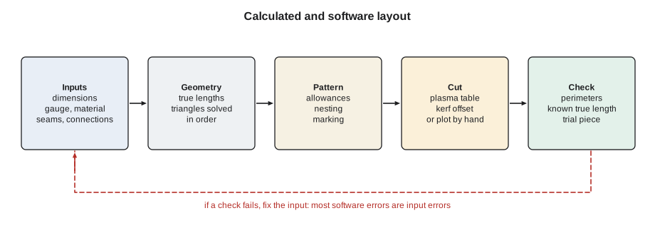
Commercial duct and fitting software takes calculated layout much further. The worker chooses a fitting from a library, such as a square-to-round, an offset transition, a gore elbow, a boot or a breeches, and enters its dimensions, the gauge, the seam types and the connection types. The software develops the pattern, adds the allowances from the shop's own settings, nests the parts on the sheet to reduce waste, and sends the cutting path to the plasma table or a cutting plotter. Many packages also produce the shop drawing, labels and the material list. SMW-420 covers shop drawings, nesting and CNC cutting in detail; here the point is what the software does with the geometry.
Inside, the software is doing exactly what this course has done by hand. It divides round ends into many more spaces than a person would, often dozens, so its curves are smoother. It computes true lengths and triangles in floating point, so it has no drawing error. It applies allowances by offsetting the outline by the shop's seam and connection settings. And it handles oblique and twisted fittings without extra effort, which is where it saves the most time over hand layout.
Where software goes wrong
Pattern software is rarely wrong about geometry. It is often wrong about inputs, and its output looks equally convincing either way. The errors Lin had seen most often in her years of detailing were these.
- The wrong diameter convention: an outside diameter entered where the software expects inside, or the reverse, which makes every round end off by two thicknesses.
- The wrong gauge or material, which changes the mean-line correction and the allowances.
- Seam and connection settings left at another job's values, so the allowances are wrong for this job's specification.
- A fitting chosen from the library that is not quite the one on the drawing, such as an on-center square-to-round where the drawing shows an offset.
- Dimensions taken from the drawing when the field had already measured different ones.
None of these is caught by the software itself, because each produces a valid pattern for the wrong fitting. They are caught by people who check the output against something independent: a perimeter, a hand-drawn pattern, a trial piece, or the drawing itself. That is why the hand methods stay in the course and on the exam.
Checking a calculated or software pattern
The checks are the ones used throughout this course, applied to the output.
- The edges that come from a straight end add up to that end's true perimeter.
- The curve along a round end equals the mean circumference, within the expected shortfall of its chords.
- The seam lines, which become one edge when the fitting is closed, are the same length on both sides.
- A known true length, such as a corner fan's outer line, measures correctly on the cut piece.
- For a new fitting type or a new setting, a trial piece formed and fitted before the batch is cut.
On the Ashgrove return boots, Kai's checks took about ten minutes for the first piece. The batch of twenty was then cut on the table without further checks, apart from a quick tape on the first piece from each sheet to confirm that the material had been loaded the right way up.
Plotting, kerf and marking
When a pattern is cut by machine, the cut has width. A plasma arc removes a strip of metal, the kerf, roughly 1/32 to 1/16 in wide depending on the torch and the thickness. The software offsets the cutting path by half the kerf so that the part comes out at its true size, but only if the kerf setting matches the torch and consumables in use. A pattern cut with the wrong kerf setting is uniformly too large or too small, which the perimeter check catches.
Machines can also mark the parts as they cut them: bend lines, part numbers, the fitting's location and the seam types. Marked bend lines save layout time at the brake, and part numbers save confusion at assembly. On hand-plotted patterns, the same information is written on the sheet in marker, and Keelson's rule was that every pattern, plotted or cut, carried its job, its fitting number and the initials of the person who checked it.
Common mistakes
MistakeTrusting a calculated pattern because the numbers look precise.
InsteadCheck perimeters and a known true length on the output; precise numbers can still come from wrong inputs.
MistakeUsing a spreadsheet or script that has never been tested against a hand pattern.
InsteadTest every template or script on a hand-drawn fitting before using it on a job.
MistakeLeaving seam and connection settings from the last job.
InsteadSet allowances for this job's specification before generating patterns.
MistakeEntering outside diameter where the software expects inside.
InsteadKnow each program's diameter convention and enter accordingly.
MistakeCutting a batch without a first-piece check.
InsteadCheck the first piece, and a trial fitting for any new type or setting.
Summary and key terms
- Calculated layout describes a pattern by numbers: true lengths, radii, angles and point coordinates.
- The ordinate method plots any pattern from a base line with a tape and a square.
- Triangulation in numbers is the two-arc crossing: a along the known edge and h square to it.
- Spreadsheets, scripts and pattern software all do the same geometry; they must be tested against hand patterns.
- Software rarely errs in geometry but often in inputs: diameter convention, gauge, allowances, fitting type and field dimensions.
- Check every new output by perimeters, a known true length and a trial piece; set the kerf correctly for machine cutting.
- Calculated layout
- Producing a pattern from computed lengths and coordinates rather than from a drawing.
- Ordinate
- A distance measured square to a base line, used to plot a pattern point.
- Abscissa
- A distance measured along a base line to the foot of an ordinate.
- Pattern software
- Software that develops fitting patterns from dimensions and settings.
- Kerf
- The width of metal removed by a cutting process such as plasma.
- Nesting
- Arranging patterns on a sheet to reduce waste.
- First-piece check
- Checking the first part of a batch before cutting the rest.
Practice problems
Work each problem on paper first, then reveal the answer to check.
Two pattern points are 12 in apart. A new point is 16 in from the first and 20 in from the second. How far along the line from the first point is the foot of its ordinate?
Show answer
a = (16² − 20² + 12²) / (2 × 12) = 0, so the foot is at the first point and the ordinate is 16 in.
What does a perimeter check confirm on a software pattern?
Show answer
That the pattern's straight edges add to the true perimeter of that end, catching wrong inputs or kerf settings.
Name two common input errors in pattern software.
Show answer
Wrong diameter convention, wrong gauge, old seam settings, the wrong fitting type, or outdated dimensions.
Why must a new spreadsheet template be tested against a hand-drawn pattern?
Show answer
Formulas are easy to break and hard to check, and a wrong template gives confident wrong patterns.
Lesson quiz · 5 questions
Score 60% or more to complete this lesson.
Create a free account to save your progress, take quizzes and earn a certificate.