
ROB-440 · Lesson 8 of 12 · 29 min
Safeguarding a robot cell
Industrial robots move fast, carry heavy loads and can start without warning when a program resumes. Most serious robot injuries have happened not during normal production but when people entered the cell to clear jams, teach, adjust or maintain the robot. Safeguarding is the set of measures that prevents these injuries: the risk assessment that identifies hazards, the guards and protective devices that keep people away from hazards or stop the robot when they approach, the safety-rated control system that makes those devices reliable, and the procedures for working inside. ROB-430 covered collaborative applications, in which people and robots deliberately share space, including protective separation distances and power and force limits. This lesson covers conventional cells, in which people are kept out during automatic operation, and the functional safety engineering behind every safeguard. It introduces the framework; designing safety systems also requires the full standards and, in most organizations, trained safety specialists, and HSE-223 and ROB-450 go further.
Laws and standards
In the United States, the Occupational Safety and Health Administration (OSHA) has no standard specific to industrial robots. Instead, OSHA enforces its general machine guarding requirement in 29 CFR 1910.212, the control of hazardous energy (lockout/tagout) standard in 1910.147, and the General Duty Clause, section 5(a)(1) of the OSH Act, which requires employers to protect workers from recognized hazards; OSHA has used the clause in robot-related citations, often referring to industry consensus standards as evidence of feasible protection. Several states run their own OSHA-approved plans. The main technical standard is ANSI/A3 R15.06-2025, Industrial Robots and Robot Systems, published in September 2025, which adopts ISO 10218-1 and -2:2025; a US-only Part 3 on user requirements was in development at the time of writing. The ANSI B11 series, including B11.0 on machine safety and B11.19 on safeguarding performance criteria, and NFPA 79 on electrical equipment of industrial machinery complete the picture.
Both national robot standards build on international standards that you will meet repeatedly: ISO 12100 for risk assessment and risk reduction, ISO 13849-1 and IEC 62061 for the functional safety of control systems, ISO 13855 for positioning protective devices, ISO 13857 for safety distances to prevent reaching hazards, ISO 14119 for interlocking devices and ISO 13850 for emergency stop. Because ISO 10218:2025 changed terminology and requirements, cells designed to the older editions remain in service, and engineers need to know which edition applied to a given installation.
Risk assessment
Every safeguarding decision starts with a risk assessment. ISO 12100 describes the process: determine the limits of the machine, including its intended use and foreseeable misuse; identify hazards in every phase of life, including installation, production, setting, teaching, cleaning, maintenance and decommissioning; estimate the risk of each hazardous situation from the severity of possible harm and the probability of its occurrence; evaluate whether the risk is acceptable; and reduce it if not. Risk reduction follows a three-step method in order of preference: inherently safe design, such as reducing speed or force or eliminating pinch points; safeguarding and complementary protective measures; and information for use, such as warnings, training and procedures. Information alone is never an acceptable substitute for feasible guarding.
| Task phase | Example hazard in a robot cell | Typical measure |
|---|---|---|
| Automatic production | Person enters while the robot is running | Perimeter guarding with interlocked gates or presence-sensing devices |
| Loading parts | Operator reaches into the robot's path | Two-station turntable, light curtain with muting logic, or safety-rated zones |
| Teaching and programming | Unexpected motion while near the robot | Manual reduced speed, enabling device, single point of control |
| Clearing a jam | Restart while hand is in a machine or fixture | Guard locking, safe stop with standstill monitoring, recovery procedures |
| Maintenance | Stored energy in air, springs, gravity-loaded axes or capacitors | Lockout and isolation, axis support, verification of zero energy |
| Changing tools | Dropped tool, sharp edges | Tool stands, fail-safe tool changers, handling aids |
A robot cell risk assessment is a team effort involving the integrator, the user's maintenance and production staff, and safety specialists. It is documented, kept with the cell, and revisited whenever the cell is modified, because adding a new machine, a new part or a new task can create hazards the original assessment did not consider.
Guards and protective devices
Fixed guards, such as fences and panels, are the simplest and most reliable safeguard. They must be strong enough to withstand impacts and robot-thrown parts, high enough that people cannot reach over them, and placed far enough from hazards that people cannot reach through openings to danger. ISO 13857 gives tables of safety distances for reaching over, through and around barriers; for example, a fence opening the size of a finger needs only a small distance to the hazard, while larger mesh openings need much more. Fences that rise from the floor leave a small gap at the bottom, typically small enough that a foot cannot pass under.
Movable guards, such as gates and doors, are interlocked so that opening them stops hazardous motion. ISO 14119 classifies interlocking devices and describes how to prevent them being defeated, for instance by using coded actuators rather than simple switches that can be taped over. Guard locking keeps a door locked until hazardous motion has stopped, which is needed when the robot or a machine takes longer to stop than a person takes to reach the hazard after opening the door.
Presence-sensing devices detect people without a physical barrier. Light curtains detect a person passing through a plane; safety laser scanners detect a person in a programmable two-dimensional area; pressure-sensitive mats detect a person standing on them; and safety-rated 3D cameras are becoming more common. These devices are electro-sensitive protective equipment (ESPE) and must be safety-rated, positioned at a sufficient distance from the hazard, and integrated into a safety-rated control system.
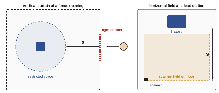
The minimum distance follows the logic introduced in ROB-430: a person approaching at speed \( K \) must not reach the hazard during the overall stopping time \( T \) of the device, the safety controller and the robot, plus an allowance for how far a body part can intrude before detection. For a horizontal detection field, such as a scanner or mat approached at floor level, the form long used in ISO 13855 is as follows, where \( H \) is the height of the detection plane in millimeters. The 2024 edition of ISO 13855 reorganizes these supplements and adds terms for moving hazards, so engineers must take formulas and conditions from the current edition.
Worked problem
Sizing a safety scanner field in front of a load station
A safety laser scanner mounted to give a detection plane 150 mm above the floor protects the approach to a robot load station. The scanner responds in 0.08 s, the safety controller in 0.02 s, and the robot's measured stopping time from full speed with its maximum payload is 0.42 s. Find the minimum distance from the hazard to the edge of the protective field.
Show solution
- Overall stopping time: \( T = 0.08 + 0.02 + 0.42 = 0.52 \) s.
- Approach term: \( 1600 \times 0.52 = 832 \) mm.
- Intrusion term: \( 1200 - 0.4 \times 150 = 1140 \) mm, which exceeds the 850 mm minimum.
- Minimum distance: \( 832 + 1140 = 1972 \) mm, plus any additional allowance for scanner measurement tolerance specified by the manufacturer.
Answer: About 2.0 m from the hazard. Reducing the robot's stopping time, for example with safety-rated speed limits near the station, directly shrinks the field.
Stopping time must be measured on the real cell, under worst-case conditions of speed, payload and extension, using a stop-time measuring instrument. It can grow as brakes wear, so many plants re-measure periodically and design with margin. Robot controllers with safety-rated speed and zone monitoring can reduce the speed when the robot is near a load station, cutting stopping time and therefore the required distance.
Emergency stop, stop categories and operating modes
Every robot has emergency stop devices on the teach pendant and at operator stations, conforming to ISO 13850 and wired into the safety system. An emergency stop is a complementary measure for when something has already gone wrong; it does not replace guarding. IEC 60204-1 defines stop categories: category 0 removes power to the drives immediately, an uncontrolled stop; category 1 brings the robot to a controlled stop with power available to the drives and then removes power; category 2 is a controlled stop that leaves power applied, with standstill monitored. Robots commonly use category 1 for emergency and protective stops, because a controlled stop keeps the robot on its path and stops it sooner than coasting against the brakes.
Industrial robots have operating modes, selected by a key switch or a password-protected selector. In automatic mode, the robot runs its program at full speed and safeguards keep people out. In manual reduced-speed mode, used for teaching, the TCP speed is limited to 250 mm/s, the person holds an enabling device, and the robot moves only while it is held. The enabling device is a three-position switch: released and fully pressed both stop motion, because a startled person tends either to let go or to clench. A manual high-speed mode for verifying programs at production speed is allowed only with additional precautions. The teach pendant also enforces a single point of control, so that no one can start the robot remotely while someone is inside with the pendant.
Functional safety: how reliable must a safeguard be?
A guard interlock or light curtain is only useful if the control system actually stops the robot when it is triggered. The functional safety standards ask how reliable each safety function must be, and how to show that a design achieves it. ISO 13849-1, whose current edition was published in 2023, expresses reliability as a performance level (PL) from a, the lowest, to e, the highest, defined by the average probability of a dangerous failure per hour (PFHd). IEC 62061 uses safety integrity levels (SIL) 1 to 3 for similar purposes.
| Performance level | PFHd range (dangerous failures per hour) | Rough SIL equivalent |
|---|---|---|
| a | \( 10^{-5} \) to below \( 10^{-4} \) | None |
| b | \( 3 \times 10^{-6} \) to below \( 10^{-5} \) | SIL 1 |
| c | \( 10^{-6} \) to below \( 3 \times 10^{-6} \) | SIL 1 |
| d | \( 10^{-7} \) to below \( 10^{-6} \) | SIL 2 |
| e | \( 10^{-8} \) to below \( 10^{-7} \) | SIL 3 |
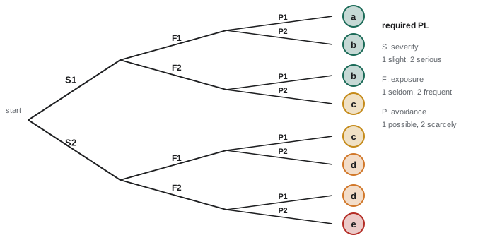
The required performance level, PLr, for each safety function is determined from the risk, commonly with a risk graph that considers the severity of injury (S1 slight and reversible, S2 serious or irreversible), the frequency and duration of exposure (F1 seldom or short, F2 frequent or long), and the possibility of avoiding the hazard (P1 possible, P2 scarcely possible). The 2023 edition also allows the probability of the hazardous event occurring to be considered in some cases. Robot safety standards have long specified PL d with a redundant, monitored architecture as the baseline for many robot safety functions, unless a risk assessment justifies otherwise, and the 2025 editions specify required performance function by function.
Worked problem
Required performance level for a gate interlock
Operators enter a palletizing cell through an interlocked gate several times a shift to remove full pallets. A robot moving at full speed could cause serious injury, and a person inside would have little chance of avoiding it. What PLr does the risk graph give?
Show solution
- Severity: serious injury possible, so S2.
- Exposure: several entries per shift, so frequent, F2.
- Avoidance: scarcely possible at full robot speed, P2.
- S2, F2, P2 gives PLr = e on the risk graph.
- Redesigning so that operators exchange pallets from outside, through a light curtain with muting or a pallet conveyor, would reduce exposure and may change the result.
Answer: PL e. Many integrators reduce exposure by redesign so that routine pallet changes do not require entering the cell.
A safety function is a chain: an input device such as an interlock switch or light curtain, a logic unit such as a safety relay or safety PLC, and output devices such as the robot's safety stop input, contactors or safe torque off in drives. The achieved PL depends on the architecture, expressed as a category from B to 4 describing redundancy and monitoring; the mean time to dangerous failure of components; the diagnostic coverage; and protection against common cause failures. For a first estimate, the PFHd values of the subsystems in the chain add.
# Combining subsystem PFHd values and finding the achieved performance level
pl_bands = [("e", 1e-8, 1e-7), ("d", 1e-7, 1e-6), ("c", 1e-6, 3e-6), ("b", 3e-6, 1e-5), ("a", 1e-5, 1e-4)]
def achieved_pl(pfh):
    for pl, lo, hi in pl_bands:
        if lo <= pfh < hi:
            return pl
    return "e or better" if pfh < 1e-8 else "below a"
chains = {
    "gate interlock (coded, dual channel) + safety PLC + robot safe stop": [2.5e-9, 5.0e-9, 4.0e-8],
    "light curtain type 4 + safety relay + two contactors": [1.2e-8, 2.0e-9, 1.1e-7],
    "single-channel switch + standard relay": [2.0e-6, 1.0e-6],
}
for name, parts in chains.items():
    total = sum(parts)
print(f"{name}: PFHd = {total:.2e} per hour -> PL {achieved_pl(total)}")gate interlock (coded, dual channel) + safety PLC + robot safe stop: PFHd = 4.75e-08 per hour -> PL e light curtain type 4 + safety relay + two contactors: PFHd = 1.24e-07 per hour -> PL d single-channel switch + standard relay: PFHd = 3.00e-06 per hour -> PL b
Note that a PFHd value alone does not establish a PL: the architecture and other requirements must also be met, and software in safety PLCs must be developed under the rules of the standard. Manufacturers' calculation tools, such as the free SISTEMA software published by Germany's Institute for Occupational Safety and Health (IFA), help engineers do the full calculation. After design comes validation under ISO 13849-2: analysis and testing to show that each safety function works as specified, including fault testing such as disconnecting one channel of a dual-channel interlock and confirming the fault is detected.
Safety-rated robot functions
Modern robot controllers include safety-rated functions that reduce guarding and improve productivity: safety-rated axis and space limiting to shrink the restricted space; tool orientation limits so that a torch never points at an operator station; safety-rated reduced speed; monitored standstill; and safe inputs and outputs connected to the cell's safety PLC over safety protocols such as CIP Safety, PROFIsafe or Safety over EtherCAT (FSoE). These protocols send safety data over the standard network with additional checks, so that corrupted or delayed messages cause a safe stop. Safety configurations are protected by passwords and checksums, recorded at commissioning, and verified periodically.
Working inside the cell
Even with excellent guarding, people must sometimes enter. Teaching uses manual reduced-speed mode with an enabling device. Maintenance and repair require hazardous energy control under OSHA 29 CFR 1910.147: machinery is stopped, energy sources are isolated and locked out, and zero energy is verified before work where unexpected start-up could cause injury, with ANSI/ASSP Z244.1 giving consensus guidance. The standard has a minor servicing exception for routine, repetitive tasks integral to production that are performed with alternative measures giving effective protection. Robots present special stored-energy hazards: gravity can move unbalanced axes when brakes are released, pneumatic grippers can hold or drop parts, and servo drives store energy in capacitors. Procedures should specify how each axis is supported, how air is vented and how zero energy is verified.
Training is part of safeguarding. Operators, programmers and maintenance staff each need training matched to their tasks, including how the safeguards work, why they must never be bypassed, and what to do when something goes wrong. Investigations of robot incidents frequently find bypassed interlocks, people working in automatic mode inside the cell, or programs restarted while someone was still inside, all of which training, supervision and good design aim to prevent.
Common mistakes
MistakeTreating the emergency stop as the main safeguard.
InsteadEmergency stops are complementary; guards and protective devices must prevent access during hazardous motion.
MistakeUsing datasheet stopping times to place light curtains and scanners.
InsteadMeasure stopping time on the real cell at worst-case speed, payload and extension, and re-measure periodically.
MistakeCalling a device safe because it is labeled safety-rated.
InsteadThe whole chain of input, logic and output must achieve the required PL, with validation.
MistakePlacing warnings instead of feasible guards.
InsteadFollow the three-step method: inherent design, safeguarding, then information.
MistakeAssessing only automatic production.
InsteadAssess teaching, jam clearing, maintenance and changeover, where most injuries occur.
Summary and key terms
- In the United States, OSHA enforces 1910.212, 1910.147 and the General Duty Clause, with ANSI/A3 R15.06-2025 and the B11 series as consensus standards.
- ISO 12100 risk assessment covers every task phase and reduces risk by inherent design, safeguarding, then information.
- Fixed and interlocked guards, guard locking and presence-sensing devices keep people from hazards during motion.
- Protective devices are placed using measured overall stopping time and ISO 13855 distances.
- Stop categories, emergency stops, operating modes, reduced speed of 250 mm/s and enabling devices govern stopping and teaching.
- ISO 13849-1 performance levels a to e, determined by a risk graph, set how reliable each safety function must be.
- Safety-rated robot functions, safety networks, validation, hazardous energy control and training complete the system.
- Risk assessment
- Identifying hazards, estimating and evaluating risk, and deciding on risk reduction.
- Interlocking guard
- A movable guard linked to the control system so that opening it stops hazardous motion.
- Guard locking
- A device that keeps a guard locked until hazardous motion has stopped.
- ESPE
- Electro-sensitive protective equipment such as light curtains and laser scanners.
- Stop category 1
- A controlled stop with power available to the drives, then power removed.
- Enabling device
- A three-position switch that permits motion only in its middle position.
- Performance level (PL)
- The ISO 13849-1 measure of a safety function's reliability, from a to e.
- PFHd
- Average probability of a dangerous failure per hour.
- Safe torque off
- A drive function that safely removes torque-producing power from a motor.
Practice problems
Work each problem on paper first, then reveal the answer to check.
List the three steps of risk reduction in order.
Show answer
Inherently safe design, safeguarding and complementary measures, information for use.
Overall stopping time 0.4 s, detection plane at 300 mm: minimum horizontal field distance?
Show answer
\( 640 + (1200 - 120) = 1720 \) mm.
What is the speed limit for manual reduced-speed mode?
Show answer
250 mm/s at the TCP.
Why does an enabling device stop motion when fully pressed?
Show answer
A startled person may clench the switch.
S2, F1, P2 on the risk graph gives which PLr?
Show answer
PL d.
Subsystem PFHd values of 2e-8, 1e-8 and 5e-8: total and band?
Show answer
8e-8 per hour, in the PL e band (subject to architecture requirements).
Why might stopping time increase over the life of a robot?
Show answer
Brake wear and changes in payload or speed settings.
Give one stored-energy hazard specific to robots.
Show answer
Gravity moving an axis when brakes are released, trapped air in grippers or charged drive capacitors.
Lesson quiz · 5 questions
Score 60% or more to complete this lesson.
Create a free account to save your progress, take quizzes and earn a certificate.