
ROB-440 · Lesson 2 of 12 · 27 min
Robot cell and work-cell design
A robot on its own does nothing useful. It becomes productive only as part of a cell: the robot, its controller, the end effector, the fixtures that hold parts, the feeders and conveyors that bring them, the machines it serves, the guarding that keeps people safe, and the control system that coordinates it all. Most of the engineering effort in an industrial robot project goes into designing that cell. This lesson follows the design sequence used by integrators: understand the process and the parts, lay out the cell, check reach and interference, estimate and then simulate the cycle, and plan for maintenance, changeover and safety from the start. Safeguarding gets its own lesson, Lesson 8, but it is a design input from day one, not an afterthought.
Start from the process, not the robot
Good cell design begins with a process study. What parts are handled, in what variants, at what rate, and with what tolerances? How do parts arrive: loose in bins, oriented in trays, on a conveyor, or on pallets? What happens to them in the cell: machining, welding, inspection, assembly, packing? How do they leave? What quality checks are required, and what happens to rejects? Which tasks are best left to people? An integrator usually captures this in a user requirement specification (URS) that the customer approves before a quotation, and later in a functional design specification (FDS) that describes how the cell will meet each requirement.
| Question | Why it matters | Typical source |
|---|---|---|
| Part variants, mass and size | Drives gripper design, payload and changeover | Drawings, CAD, sample parts |
| Required rate and shifts | Sets takt time and the number of robots or machines | Production plan |
| Part presentation | Determines whether vision, feeders or fixtures are needed | Process study, supplier packaging |
| Tolerances | Determines whether teaching is enough or calibration and sensing are required | Drawings, quality plan |
| Environment | Dust, coolant, washdown, temperature and explosive atmospheres affect robot and sensor choice | Site survey |
| Utilities and floor | Power, compressed air, network, floor flatness and load capacity | Plant engineering |
| Operator tasks | Loading, unloading, inspection and recovery after faults shape the layout | Interviews, task analysis |
A frequent cause of failed projects is poor part presentation. A robot that must pick parts dumped randomly in a bin needs 3D vision, a gripper that can cope with many orientations, and error recovery for failed picks, as ROB-400 showed in its bin-picking capstone. If the supplier can deliver the same parts in a molded tray, the problem becomes a simple taught pick at known positions. Changing the presentation is often the cheapest engineering decision in the whole project.
Laying out the cell
A layout drawing places the robot, machines, conveyors, fixtures, operator stations, guarding, the robot controller and electrical cabinets on the plant floor. Designers work in plan view first and then check heights and clearances in 3D. Common layout patterns include a robot in the center serving machines arranged around it, a robot on a linear track serving a row of machines, an overhead gantry above a line, and a two-station layout in which the operator loads one fixture while the robot works on another.
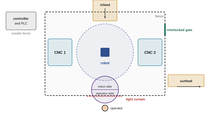
A two-position turntable or a pair of sliding drawers is a classic way to keep the robot busy while a person loads parts. The operator loads one side outside the guarded area while the robot works on the other side, then the table indexes. Because the person never enters the robot's space during normal operation, the cell can run at full robot speed behind ordinary guarding. Lesson 8 discusses how such load stations are safeguarded.
Layout also determines access. Maintenance technicians need room to change grippers, clear jams and service the machines; quality inspectors may need to remove parts; forklifts must deliver material. Leaving at least the clearances required by the guarding standard between the robot's restricted space and the fence, and planning gates where people will actually need to go, prevents later modifications that weaken safety. Robot controllers and electrical cabinets are placed outside the safeguarded space so that troubleshooting does not require entry.
Reach, envelope and interference
The robot's work envelope, drawn from the datasheet, shows every point the wrist center can reach. With a tool fitted, the reachable volume shifts outward by the tool length but also gains orientation constraints: a point may be reachable only with the tool pointing in certain directions. Designers check every target with the actual tool orientation it needs, not just the position. Points near the edge of the envelope or near singularities, which ROB-210 described, are avoided because the robot slows, loses stiffness or must reconfigure its joints.
Three spaces are defined in robot safety standards. The maximum space is everything the robot, end effector and workpiece could sweep if the robot moved to every joint limit. The restricted space is the portion of the maximum space that is limited by mechanical stops or safety-rated soft axis and space limiting, which modern controllers provide through functions with names such as SafeMove, DCS (Dual Check Safety) or Safe Operation. The operating space is the part actually used by the program. Guarding is placed based on the restricted space, so limiting the restricted space with safety-rated functions allows a smaller footprint.
Worked problem
Checking reach to a machine chuck
A robot's wrist center can reach 1,650 mm from axis 1. The gripper extends 220 mm from the wrist center. A lathe chuck center is 1,500 mm horizontally from the robot base axis and 300 mm above the shoulder height, and the gripper must approach horizontally along the chuck axis, which points directly at the robot. Can the robot reach it with reasonable margin?
Show solution
- With a horizontal approach toward the robot, the wrist center sits 220 mm closer to the robot than the gripping point: \( 1500 - 220 = 1280 \) mm horizontally.
- The distance from shoulder to wrist center is \( \sqrt{1280^2 + 300^2} \approx 1315 \) mm, ignoring the small offset between axis 1 and the shoulder.
- That is about 80 percent of the 1,650 mm maximum, leaving room for the extraction stroke of perhaps 100 mm.
- A simulation must still confirm that the arm clears the machine door frame and that joint limits allow the required wrist angles.
Answer: Yes, roughly 80 percent of reach with margin for the extraction stroke; confirm in simulation with the real machine model.
Fixturing and part location
Fixtures hold parts in known positions so that taught points remain valid. The classic 3-2-1 principle locates a prismatic part with three points on a primary face, two on a secondary face and one on a tertiary face, constraining all six degrees of freedom with the minimum of contacts. Clamps then hold the part against those locators without disturbing its position. Robot fixtures must also be robust to how robots load parts: lead-in chamfers, slightly oversized nests and compliance in the gripper allow small errors without jamming.
Tolerance stack-ups decide whether a cell can rely on teaching alone. If the part position in the fixture varies by ±0.3 mm, the fixture is placed within ±0.1 mm, the robot repeats to ±0.05 mm, and the gripper fingers have ±0.1 mm play, the worst-case error is the sum, ±0.55 mm, while a statistical estimate using the root sum of squares is about ±0.34 mm. If the insertion requires ±0.2 mm, the cell needs better fixtures, chamfers, a compliant wrist or sensing.
# Worst-case vs root-sum-square vs Monte Carlo tolerance stack
import numpy as np
rng = np.random.default_rng(440)
tol = {"part in fixture": 0.30, "fixture placement": 0.10,
       "robot repeatability": 0.05, "finger play": 0.10}       # +/- mm
worst = sum(tol.values())
rss = np.sqrt(sum(t**2 for t in tol.values()))
# treat each tolerance as +/-3 sigma of a normal distribution
samples = sum(rng.normal(0, t / 3, 200_000) for t in tol.values())
print(f"worst case  +/-{worst:.2f} mm")
print(f"RSS         +/-{rss:.2f} mm")
print(f"share of parts within +/-0.20 mm: {np.mean(abs(samples) <= 0.20):.1%}")worst case +/-0.55 mm RSS +/-0.34 mm share of parts within +/-0.20 mm: 92.6%
Cycle time analysis
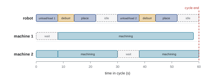
Lesson 1 introduced takt time. During design, the cell's cycle time is built up from every robot motion, gripper action, machine operation and waiting period. Engineers draw a sequence chart, also called a Gantt chart or time-and-motion chart, showing what each resource is doing over one cycle. The chart reveals which resource is the bottleneck and where the robot is idle.
Worked problem
One robot, how many machines?
A CNC lathe has a 150 s machining cycle. For each machine, the robot needs 12 s to open the door, unload, load and close the door, and another 8 s to move the finished part to a gauge and then the outfeed. How many lathes can one robot keep busy, and what is the cell output?
Show solution
- Robot time per machine per cycle: \( 12 + 8 = 20 \) s.
- During the 150 s machining time the robot can serve other machines. A machine's full cycle is \( 150 + 12 = 162 \) s, since it waits during loading.
- Robot capacity: \( 162 / 20 = 8.1 \), so in principle up to 8 machines, but walking distance between machines adds travel time.
- With a realistic 6 s travel between machines, robot time per machine is 26 s, giving \( 162 / 26 \approx 6.2 \), so 6 machines.
- Output with 6 machines: \( 6 \times 3600 / 162 \approx 133 \) parts per hour.
Answer: About 6 machines with travel included, giving roughly 133 parts an hour; in practice most cells serve 1 to 4 machines because of floor space and the cost of a long track.
Common ways to shorten a robot cycle include dual grippers, so the robot can unload a finished part and load a new one without a trip to the outfeed in between; parallel motions, such as moving the robot while the gripper opens; avoiding wrist reorientation; reducing approach and retract distances; and using blended or fly-by points, called zones or continuous paths depending on the vendor, instead of exact stops at intermediate points. Each exact stop costs time to decelerate, settle and accelerate.
Simulation and digital twins
Robot simulation software, either from the robot vendor or from independent suppliers, models the robot's kinematics, its controller's motion planner, the tooling, fixtures and machines. Vendor tools typically include a virtual controller running the same software as the real one, which gives cycle-time predictions within a few percent. Simulation is used to choose robot models, verify reach and interference, estimate cycle time, generate and test programs offline (Lesson 4), and present the concept to the customer.
A digital twin goes further: it is a model connected to the real cell, updated with live data, used for virtual commissioning before installation and for diagnosing problems after. In virtual commissioning, the real PLC program and robot programs run against a simulated cell, so that logic errors are found at a desk instead of on the shop floor with the customer watching. Studies and vendor case reports commonly claim that virtual commissioning shortens on-site commissioning substantially, though the size of the benefit depends on the quality of the model. ROB-360 covered simulation fundamentals; here the emphasis is on using them to make a commercial decision.
| Design stage | Simulation question | Typical fidelity |
|---|---|---|
| Concept | Which robot model and layout can reach everything and meet takt? | Robot kinematics, simple solids, estimated cycle |
| Detailed design | Do tooling, cables and guarding clear everything? What is the exact cycle? | Virtual controller, detailed CAD, dress pack models |
| Programming | Can the paths be generated offline and downloaded? | Calibrated cell model, real I/O names |
| Virtual commissioning | Does the PLC and robot logic handle every sequence and fault? | Simulated sensors and actuators connected to real controllers |
| Operation | Why did cycle time drift? What if we add a product? | Digital twin fed with production data |
Designing for changeover, maintenance and recovery
A cell that runs perfectly on one part is easy to design. A cell that changes over between ten variants in five minutes, recovers from a dropped part without an engineer, and lets a technician change the gripper fingers safely is much harder and much more valuable. Design for changeover includes quick-change fingers with poka-yoke features that prevent wrong installation, recipes in the PLC that select the right program and parameters, and sensors that confirm the right tooling is fitted. Design for recovery includes clear fault messages on the operator panel, defined home positions, and programs that can resume from any step after a stop. Lesson 10 returns to maintainability.
Integrators often say that half of the programming effort goes into the abnormal cases: missing parts, failed grips, machine alarms, power loss in the middle of a cycle, and an operator opening the door at the wrong moment. A sequence chart that only covers the normal cycle is therefore only half a design.
Common mistakes
MistakeChoosing the robot first and fitting the process around it.
InsteadStudy parts, presentation, rates and tolerances first, then choose the robot and layout.
MistakeChecking reach with position only.
InsteadCheck each target with the tool orientation it needs and keep away from envelope edges and singularities.
MistakeAdding worst-case tolerances only, or RSS only, without thinking.
InsteadUse worst case for safety-critical fits and RSS or Monte Carlo for realistic yield estimates.
MistakeIgnoring exact stops when estimating cycle time.
InsteadUse blended motions where accuracy is not needed and simulate with a virtual controller.
MistakeDesigning only the normal sequence.
InsteadDesign recovery from missing parts, failed grips, faults and power loss from the start.
Summary and key terms
- Cell design starts from the process: parts, rates, presentation, tolerances, environment and operator tasks.
- Layouts such as central robots, tracks, gantries and two-station turntables balance throughput, footprint and access.
- Maximum, restricted and operating spaces define where guarding goes; safety-rated limits can shrink the restricted space.
- Fixtures use the 3-2-1 principle; tolerance stack-ups decide whether teaching is enough.
- Sequence charts identify the bottleneck and robot idle time; dual grippers and blended motions shorten cycles.
- Simulation and virtual commissioning catch reach, interference, timing and logic errors before installation.
- Changeover, maintenance and fault recovery must be designed in, not added later.
- Work cell
- A robot together with its tooling, fixtures, machines, guarding and controls.
- User requirement specification (URS)
- A document stating what the customer needs the cell to do.
- Restricted space
- The portion of the robot's maximum space limited by stops or safety-rated limiting functions.
- 3-2-1 principle
- Locating a part with three, two and one contact points on three faces to fix six degrees of freedom.
- Root sum of squares (RSS)
- A statistical estimate of combined independent tolerances.
- Sequence chart
- A time chart showing what each resource does during one cycle.
- Virtual commissioning
- Testing real control programs against a simulated cell before installation.
- Digital twin
- A model of a real system updated with live data and used for analysis and decisions.
Practice problems
Work each problem on paper first, then reveal the answer to check.
Why is a two-position turntable common in robot cells?
Show answer
The operator loads one side while the robot works on the other, so the robot stays busy and people stay out of its space.
Tolerances of ±0.2, ±0.1 and ±0.05 mm: worst case and RSS?
Show answer
Worst case ±0.35 mm; RSS \( \sqrt{0.04 + 0.01 + 0.0025} \approx \) ±0.23 mm.
A machine cycle is 120 s and the robot needs 30 s per machine including travel. How many machines can it serve?
Show answer
If loading takes about 10 s, the machine cycle is about 130 s, so \( 130/30 \approx 4.3 \), or 4 machines.
What is the difference between restricted and operating space?
Show answer
Restricted space is limited by stops or safety functions; operating space is what the program actually uses.
Name two ways to shorten robot cycle time.
Show answer
Dual grippers, blended motions, shorter approach distances, avoiding wrist reorientation.
What does virtual commissioning test?
Show answer
Real PLC and robot programs against a simulated cell, including sequences and faults.
Why put the robot controller outside the fence?
Show answer
So that troubleshooting and resetting do not require entry into the safeguarded space.
What document describes how the integrator will meet each requirement?
Show answer
The functional design specification (FDS).
Lesson quiz · 5 questions
Score 60% or more to complete this lesson.
Create a free account to save your progress, take quizzes and earn a certificate.