
ROB-300 · Lesson 6 of 12 · 35 min
State feedback, pole placement and observers
PID control looks only at the output error and its derivative and integral. State-space control looks at the whole internal state of the system, positions, velocities, and for a flexible joint the twist of the transmission, and feeds back a weighted combination of all of it. With full state feedback, every closed-loop pole can be placed anywhere we like, provided the system is controllable. This is a big advantage for systems with more than two states, such as the flexible joint of lesson 3, where PD feedback from the motor angle alone cannot damp the link's oscillation. The catch is that not every state is measured. An observer, a real-time simulation of the plant corrected by the measurements, estimates the missing states. This lesson builds both halves: state feedback with pole placement, including Ackermann's formula, and the Luenberger observer, joined by the separation principle. It uses the state-space models of ROB-230.
State-space models of joints
A linear system in state-space form is \( \dot{\mathbf{x}} = \mathbf{A}\mathbf{x} + \mathbf{B}u \), \( y = \mathbf{C}\mathbf{x} \). For the rigid joint of lesson 4, choose the state \( \mathbf{x} = [q, \dot{q}]^{\mathsf{T}} \) and input \( u = \tau \):
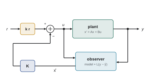
For the flexible joint, the state grows to four elements, motor angle and speed and link angle and speed, \( \mathbf{x} = [\theta_1, \dot{\theta}_1, \theta_2, \dot{\theta}_2]^{\mathsf{T}} \), with the torque acting on the motor side only. The eigenvalues of A are the open-loop poles. State feedback replaces the input with \( u = -\mathbf{K}\mathbf{x} + k_rr \), where K is a row of gains and r is the reference, giving the closed-loop dynamics
The closed-loop poles are the eigenvalues of \( \mathbf{A} - \mathbf{B}\mathbf{K} \), and choosing K to put them in chosen places is called pole placement.
Pole placement for the rigid joint
For the rigid joint, \( \mathbf{K} = [k_1, k_2] \) gives \( \mathbf{A} - \mathbf{B}\mathbf{K} = \begin{bmatrix} 0 & 1 \\ -k_1/J & -(b + k_2)/J \end{bmatrix} \) with characteristic polynomial \( s^2 + \frac{b + k_2}{J}s + \frac{k_1}{J} \). Matching this to the desired \( s^2 + 2\zeta\omega_ns + \omega_n^2 \) gives \( k_1 = J\omega_n^2 \) and \( k_2 = 2\zeta\omega_nJ - b \): exactly the PD gains of lesson 4. For a second-order plant, state feedback is PD control. Its extra power appears with more states.
Worked problem
Reference gain for zero steady error
With state feedback \( u = -\mathbf{K}\mathbf{x} + k_rr \) on the rigid joint (J = 1.5, b = 0.5, \( k_1 \) = 600, \( k_2 \) = 59.5), what reference gain \( k_r \) makes q settle at r in the absence of disturbance?
Show solution
- At steady state \( \dot{q} = 0 \) and \( \ddot{q} = 0 \), so \( 0 = -k_1q + k_rr \).
- For q = r we need \( k_r = k_1 = 600 \).
Answer: \( k_r = 600 \), so \( u = 600(r - q) - 59.5\dot{q} \), which is PD control with the derivative on the measurement. A constant disturbance would still cause steady error; adding an integral state, as shown later in this lesson, removes it.
Controllability
Pole placement is possible only if the input can influence every state. A system is controllable if, for any initial and final state, some input drives it from one to the other in finite time. For a system with n states, the test is the rank of the controllability matrix:
If the system is controllable, state feedback can place all n poles arbitrarily (complex poles in conjugate pairs). If it is not, some modes are untouched by the input and keep their open-loop poles whatever K is; if any of those are unstable, no controller can stabilize the system. Controllability also has a practical, graded meaning: a nearly singular \( \mathcal{C} \) means that some modes can be moved only with very large gains and torques.
Worked problem
Testing controllability
Is the rigid joint (J = 1.5, b = 0.5) controllable? What if two identical uncoupled joints were driven by one motor torque applied equally to both?
Show solution
- Single joint: \( \mathbf{A}\mathbf{B} = [1/J, -b/J^2]^{\mathsf{T}} \). \( \mathcal{C} = \begin{bmatrix} 0 & 0.667 \\ 0.667 & -0.222 \end{bmatrix} \) has determinant −0.444 ≠ 0, so rank 2: controllable.
- Two identical joints with the same input: the four-state system has two identical copies of each mode, and the difference between the joints' states, \( q_a - q_b \), obeys the free dynamics regardless of u.
- So rank \( \mathcal{C} \) = 2 < 4: not controllable.
Answer: One joint is controllable. Two identical joints driven by one common torque are not: the input can move their average but never their difference. Physically this is obvious; the test catches the same problem in systems where it is far from obvious.
Ackermann's formula
For larger systems, matching polynomial coefficients by hand is tedious. Ackermann's formula computes the gain directly for a single-input controllable system. If the desired characteristic polynomial is \( \alpha_c(s) = s^n + a_{n-1}s^{n-1} + \cdots + a_0 \), then
The formula is exact but numerically sensitive for large n; software uses more robust algorithms, but Ackermann is ideal for understanding and for small systems.
Worked problem
Ackermann for the rigid joint
Use Ackermann's formula to place both poles of the rigid joint (J = 1.5, b = 0.5) at −20.
Show solution
- Desired polynomial: \( (s + 20)^2 = s^2 + 40s + 400 \).
- \( \mathbf{A}^2 = \begin{bmatrix} 0 & -1/3 \\ 0 & 1/9 \end{bmatrix} \) (since \( b/J = 1/3 \)). \( \alpha_c(\mathbf{A}) = \mathbf{A}^2 + 40\mathbf{A} + 400\mathbf{I} = \begin{bmatrix} 400 & 39.667 \\ 0 & 386.78 \end{bmatrix} \).
- \( \mathcal{C}^{-1} = \begin{bmatrix} 0.5 & 1.5 \\ 1.5 & 0 \end{bmatrix} \), so the last row is [1.5, 0].
- \( \mathbf{K} = [1.5, 0]\,\alpha_c(\mathbf{A}) = [600, 59.5] \).
Answer: \( \mathbf{K} = [600, 59.5] \), identical to the PD gains for critical damping at 20 rad/s, as expected.
State feedback for the flexible joint
The flexible joint is where state feedback shows its value. With motor-side PD alone, the controller can damp the motor but has little influence on the link's oscillation against the transmission spring; the closed loop then has a lightly damped pair near the joint resonance that rings after every move. With all four states fed back, including the link angle and speed or equivalently the transmission twist and its rate, all four poles can be placed, so the resonant pair can be given proper damping. Industrial robots with link-side encoders or torque sensors in each joint, including most collaborative arms, use exactly this structure, often written as motor PD plus feedback of joint torque and its derivative.
Observability and the Luenberger observer
State feedback needs the whole state, but sensors measure only some of it. Velocity is usually estimated from encoder position, and on many joints the link angle is not measured at all. An observer estimates the state by running a copy of the model in parallel with the plant and correcting it with the measurement error:
Subtracting this from the plant equation gives the dynamics of the estimation error \( \mathbf{e} = \mathbf{x} - \hat{\mathbf{x}} \): \( \dot{\mathbf{e}} = (\mathbf{A} - \mathbf{L}\mathbf{C})\mathbf{e} \). Choosing the observer gain L places the eigenvalues of \( \mathbf{A} - \mathbf{L}\mathbf{C} \), so the error dies out at a chosen rate. This is the dual of pole placement, and it is possible for every pole if and only if the system is observable:
Observer poles are normally placed two to six times faster than the controller poles, so the estimate converges before the controller relies on it, but not so fast that measurement noise is amplified excessively. The Kalman filter of ROB-310 chooses L optimally given noise statistics; the Luenberger observer chooses it by pole placement.
Worked problem
A velocity observer for an encoder joint
For the rigid joint with position measured (C = [1, 0]), design L to place both observer poles at −100.
Show solution
- \( \mathbf{A} - \mathbf{L}\mathbf{C} = \begin{bmatrix} -l_1 & 1 \\ -l_2 & -b/J \end{bmatrix} \), with characteristic polynomial \( s^2 + (l_1 + b/J)s + (l_1b/J + l_2) \).
- Desired: \( (s + 100)^2 = s^2 + 200s + 10{,}000 \).
- \( l_1 = 200 - 0.333 = 199.67 \); \( l_2 = 10{,}000 - 199.67 \times 0.333 = 9{,}933.4 \).
Answer: \( \mathbf{L} = [199.7, 9933]^{\mathsf{T}} \). The observer's velocity estimate converges with a time constant of about 10 ms and, unlike a raw finite difference, uses the torque input and the model to fill in between encoder counts, giving a much smoother velocity signal.
The separation principle and integral action
When the controller uses the estimate, \( u = -\mathbf{K}\hat{\mathbf{x}} \), the combined system of plant and observer has 2n poles: the n controller poles, eigenvalues of \( \mathbf{A} - \mathbf{B}\mathbf{K} \), and the n observer poles, eigenvalues of \( \mathbf{A} - \mathbf{L}\mathbf{C} \). This is the separation principle: controller and observer can be designed independently, and putting them together does not move either set of poles. It holds exactly for linear models; with model error it holds approximately, which is one reason to keep observer and controller poles well separated.
State feedback, like PD control, leaves a steady error under a constant disturbance. The cure is to add an integral state \( x_I = \int (r - q)\,dt \) to the state vector and place the poles of the augmented system, \( u = -\mathbf{K}\mathbf{x} + k_Ix_I \). For the rigid joint this produces exactly the PID structure of lesson 4, with all three poles placed at once.
Worked problem
Augmented integral state
Add an integral state to the rigid joint (J = 1.5, b = 0.5) and place all three poles at −15. Compare with lesson 4.
Show solution
- Augmented state \( [x_I, q, \dot{q}] \) with \( \dot{x}_I = r - q \). Control \( u = k_Ix_I - k_1q - k_2\dot{q} \).
- Closed-loop characteristic polynomial: \( Js^3 + (b + k_2)s^2 + k_1s + k_I = 0 \).
- Match \( 1.5(s + 15)^3 \): \( k_2 = 67.0 \), \( k_1 = 1012.5 \), \( k_I = 5062.5 \).
Answer: The gains equal the PID gains of lesson 4 (\( K_d \), \( K_p \), \( K_i \)). State-space design reproduces PID for the simple joint and extends naturally to the flexible joint, multiple outputs and the optimal design of lesson 7.
Numerical design for the flexible joint
The code below builds the four-state flexible-joint model of lesson 3, checks controllability with the motor torque as input and observability with only the motor encoder as output, and uses Ackermann's formula to place all four closed-loop poles: a pair representing the gross motion and a well-damped pair near the resonance.
import numpy as np
J1, J2, k, c = 1.2, 0.78, 3.0e4, 5.0                # joint-side values from lesson 3
A = np.array([[0, 1, 0, 0],
              [-k/J1, -c/J1, k/J1, c/J1],
              [0, 0, 0, 1],
              [k/J2, c/J2, -k/J2, -c/J2]])
B = np.array([[0], [1/J1], [0], [0]])
C = np.array([[1, 0, 0, 0]])                          # motor encoder only
Ctrb = np.hstack([np.linalg.matrix_power(A, i) @ B for i in range(4)])
Obsv = np.vstack([C @ np.linalg.matrix_power(A, i) for i in range(4)])
print("rank controllability:", np.linalg.matrix_rank(Ctrb), " rank observability:", np.linalg.matrix_rank(Obsv))
print("open-loop poles:", np.round(np.linalg.eigvals(A), 1))
wn1, z1, wn2, z2 = 30.0, 1.0, 250.0, 0.5            # desired: slow pair and damped resonance pair
coef = np.polymul([1, 2*z1*wn1, wn1**2], [1, 2*z2*wn2, wn2**2])
alpha = sum(cf*np.linalg.matrix_power(A, 4 - i) for i, cf in enumerate(coef))
K = np.array([[0, 0, 0, 1]]) @ np.linalg.inv(Ctrb) @ alpha
print("K =", np.round(K, 1))
print("closed-loop poles:", np.round(np.linalg.eigvals(A - B @ K), 1))rank controllability: 4 rank observability: 4 open-loop poles: [-5.3+251.9j -5.3-251.9j 0. +0.j -0. +0.j ] K = [[ 17133. 359.3 -15378. -235.6]] closed-loop poles: [-125.+216.5j -125.-216.5j -30. +0.j -30. -0.j ]
Both matrices have full rank, so the flexible joint can be fully controlled with motor torque and fully observed, in principle, from the motor encoder alone. The open-loop poles show the rigid-body pair at the origin and the lightly damped resonance near 252 rad/s; after feedback, the resonance pair has damping ratio 0.5. The gains reveal the structure: nearly equal and opposite weights on the motor and link angles (about 17,100 and −15,400 N·m/rad) amount to strong feedback of the transmission twist \( \theta_1 - \theta_2 \), with a net position gain of only about 1,750 N·m/rad, and the speed gains likewise act mostly on the twist rate. In practice those link states would be measured by a link encoder or estimated by an observer, since estimating them from the motor encoder alone is possible but sensitive to model error.
Common mistakes
MistakeTrying to place poles of an uncontrollable system
InsteadCheck the rank of the controllability matrix first; uncontrollable modes cannot be moved.
MistakePlacing observer poles slower than controller poles
InsteadMake the observer two to six times faster so the estimate converges first.
MistakePlacing observer poles extremely fast
InsteadVery high observer gains amplify measurement noise.
MistakeForgetting the reference gain in state feedback
InsteadWithout \( k_r \) or an integral state, the output does not settle at the reference.
MistakeAssuming the separation principle holds exactly on the real robot
InsteadIt is exact only for a perfect linear model; leave margin between observer and controller poles.
Summary and key terms
- State feedback \( u = -\mathbf{K}\mathbf{x} + k_rr \) places the eigenvalues of \( \mathbf{A} - \mathbf{B}\mathbf{K} \).
- For a rigid joint, state feedback reproduces PD control; with an integral state it reproduces PID.
- All poles can be placed if and only if the controllability matrix has full rank.
- Ackermann's formula gives the gain directly for single-input systems.
- Full state feedback can damp a flexible joint's resonance, which motor-side PD cannot.
- A Luenberger observer estimates states with error dynamics \( \mathbf{A} - \mathbf{L}\mathbf{C} \), possible when the system is observable.
- The separation principle lets controller and observer be designed independently.
- State feedback
- Control computed as a weighted sum of all state variables.
- Pole placement
- Choosing feedback gains to put closed-loop poles at chosen locations.
- Controllability
- The ability of the input to drive the state anywhere in finite time.
- Controllability matrix
- The matrix \( [\mathbf{B}, \mathbf{AB}, \ldots, \mathbf{A}^{n-1}\mathbf{B}] \).
- Ackermann's formula
- A closed-form expression for single-input pole-placement gains.
- Observer
- A model-based estimator of unmeasured states corrected by measurements.
- Observability
- The ability to determine the state from the outputs over time.
- Observer gain
- The matrix L weighting the measurement error in an observer.
- Separation principle
- The property that controller and observer poles are unaffected by combining them.
- Integral state
- An added state equal to the integrated tracking error, used to remove steady error.
Practice problems
Work each problem on paper first, then reveal the answer to check.
For J = 2, b = 0, what state-feedback gains give poles at −10, −10?
Show answer
\( k_1 = 200 \), \( k_2 = 40 \).
Is a double integrator \( \ddot{q} = u \) controllable?
Show answer
Yes; \( \mathcal{C} = [[0, 1], [1, 0]] \) has rank 2.
Is a double integrator observable from velocity only?
Show answer
No; position cannot be recovered from velocity alone.
How many poles does a plant plus full-order observer with 3 states have?
Show answer
Six: three controller and three observer poles.
Controller poles are at −20. Where might you place observer poles?
Show answer
Around −40 to −120.
What happens to an uncontrollable unstable mode under state feedback?
Show answer
It stays unstable; no feedback can move it.
Why does motor-side PD struggle to damp link oscillation in a flexible joint?
Show answer
It does not use the link states, so it has little authority over the resonant mode.
Give the error dynamics of a Luenberger observer.
Show answer
\( \dot{\mathbf{e}} = (\mathbf{A} - \mathbf{L}\mathbf{C})\mathbf{e} \).
Name one advantage of an observer velocity estimate over finite differencing.
Show answer
Less noise, because it uses the model and input between encoder counts.
What does adding an integral state achieve?
Show answer
Zero steady error under constant disturbances.
Lesson quiz · 5 questions
Score 60% or more to complete this lesson.
Create a free account to save your progress, take quizzes and earn a certificate.