
ROB-300 · Lesson 1 of 12 · 42 min
Rigid-body dynamics for robots
Kinematics, the subject of ROB-210, describes where a robot's links are and how fast they move without asking why. Dynamics asks why: which torques and forces produce a given motion, and what motion results from a given set of torques. A controller that ignores dynamics has to discover the robot's inertia, gravity loads and coupling effects through feedback error alone, which works for slow, light robots and fails for fast or heavy ones. A controller that knows the dynamics can predict the torque each joint needs, feed it forward and leave feedback to correct only the small remaining error. This course builds that knowledge from the ground up: rigid-body mechanics in this lesson, the equations of motion of whole manipulators in lesson 2, actuators and friction in lesson 3, and then the control methods that use them. This first lesson reviews the mechanics of a single rigid body, the building block of every robot model: mass and center of mass, the inertia tensor, the parallel axis theorem, and the Newton–Euler equations that relate forces and torques to linear and angular acceleration.
Why robots need dynamic models
Consider a shoulder joint lifting an arm. At rest the motor must hold the arm's weight against gravity; to start moving it must also supply torque to accelerate the arm's inertia; and once the elbow moves as well, the two links push and pull on each other through their connection. A pick-and-place robot moving a 5 kg part at 2 m/s accelerates and decelerates several times a second, and the inertial torques can exceed the gravity torques many times over. If the controller treats every joint as an independent, constant load, it will overshoot when the arm is stretched out and inertia is high, lag when it carries a payload and wobble when two joints move together. Dynamic models allow engineers to size motors and gearboxes before any metal is cut, to simulate a design to see whether it will meet its cycle time, to write feedforward terms that cancel gravity and inertia, and to estimate contact forces without a force sensor. They are also central to safety: collaborative robots detect collisions by comparing measured motor currents with the currents the dynamic model predicts, and flag a difference as an unexpected contact.
Mass, center of mass and linear momentum
A rigid body is an idealized object whose particles keep fixed distances from one another. Its mass m is the sum of the masses of its particles, and its center of mass is the mass-weighted average position:
For a link made of several parts, such as an aluminum tube, a motor and a gearbox, the composite center of mass is the mass-weighted average of the parts' centers of mass. The linear momentum of the body is \( m\mathbf{v}_c \), where \( \mathbf{v}_c \) is the velocity of the center of mass, and Newton's second law states that the net external force equals its rate of change:
The remarkable consequence is that the center of mass moves as if all the mass were concentrated there and every external force acted there, regardless of how the body rotates. Internal forces between parts of the body cancel in pairs. For a robot link, the external forces are gravity acting at the center of mass and the constraint forces exerted by neighboring links at the joints.
Worked problem
Center of mass of a composite link
A forearm link consists of a tube of mass 1.2 kg whose center of mass is 0.20 m from the elbow axis, and a wrist motor of mass 0.8 kg mounted 0.38 m from the elbow axis. Find the link mass and the distance of its center of mass from the elbow.
Show solution
- Total mass: \( m = 1.2 + 0.8 = 2.0 \) kg.
- Mass-weighted average along the link: \( r_c = (1.2 \times 0.20 + 0.8 \times 0.38)/2.0 \).
- \( r_c = (0.240 + 0.304)/2.0 = 0.272 \) m.
Answer: The link has m = 2.0 kg with its center of mass 0.272 m from the elbow. The heavy wrist motor near the far end pulls the center of mass outward, which raises both the gravity torque and the inertia the elbow must handle. Designers often move motors toward the base and drive distal joints through belts or cables for exactly this reason.
Rotation and the moment of inertia
Rotation about a fixed axis is governed by the rotational analog of Newton's law. If a body spins about a fixed axis with angular acceleration \( \alpha \), the net torque about that axis is \( \tau = I\alpha \), where the moment of inertia about the axis is
with r the perpendicular distance of each mass element from the axis. Inertia grows with the square of distance, so mass far from the axis costs much more than mass near it. Standard results for simple shapes are worth knowing, because real links are usually approximated as combinations of them.
| Shape and axis | Moment of inertia |
|---|---|
| Point mass m at distance r | \( mr^2 \) |
| Slender rod, length L, about its center | \( mL^2/12 \) |
| Slender rod, length L, about one end | \( mL^2/3 \) |
| Solid cylinder or disc, radius R, about its axis | \( mR^2/2 \) |
| Thin-walled tube, radius R, about its axis | \( mR^2 \) |
| Solid sphere, radius R, about a diameter | \( 2mR^2/5 \) |
| Rectangular block a × b, about axis through center perpendicular to the a–b face | \( m(a^2 + b^2)/12 \) |
The parallel axis theorem
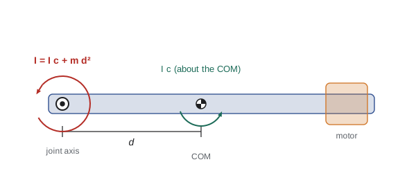
Robot joints rarely rotate a link about its own center of mass; they rotate it about a joint axis some distance away. The parallel axis theorem relates the two. If \( I_c \) is the moment of inertia about an axis through the center of mass and d is the distance to a parallel axis, then
The extra term \( md^2 \) is the inertia the body has simply because its center of mass travels in a circle. The rod results in the table confirm the theorem: \( mL^2/12 + m(L/2)^2 = mL^2/3 \). The theorem applies to each part of a composite link, after which the parts' inertias about the joint axis simply add.
Worked problem
Link inertia about the joint axis
For the forearm of the previous example, model the tube as a slender rod of length 0.40 m centered 0.20 m from the elbow, and the wrist motor as a solid cylinder of radius 0.04 m whose own axis is parallel to the elbow axis, located 0.38 m away. Find the moment of inertia of the link about the elbow axis.
Show solution
- Tube about its own center: \( 1.2 \times 0.40^2/12 = 0.0160 \) kg·m². Parallel axis term: \( 1.2 \times 0.20^2 = 0.0480 \). Tube total: 0.0640 kg·m².
- Motor about its own axis: \( 0.8 \times 0.04^2/2 = 0.00064 \) kg·m². Parallel axis term: \( 0.8 \times 0.38^2 = 0.1155 \). Motor total: 0.1162 kg·m².
- Link total: \( I = 0.0640 + 0.1162 = 0.180 \) kg·m².
Answer: About 0.18 kg·m². Almost two thirds of it comes from the motor, and nearly all of that from the md² term. Treating the motor as a point mass at 0.38 m would give 0.1155 kg·m², within 1 % of the full result, which is why point-mass models are often good enough for distant compact parts.
The inertia tensor
For rotation about a fixed axis a single number suffices, but robot links rotate in three dimensions about axes that change with configuration. The general description is the inertia tensor, a symmetric 3 × 3 matrix expressed in a frame attached to the body with origin at the center of mass:
The diagonal terms are moments of inertia about the frame's axes, for example \( I_{xx} = \int (y^2 + z^2)\,dm \), and the off-diagonal terms are products of inertia such as \( I_{xy} = \int xy\,dm \). The angular momentum about the center of mass is \( \mathbf{h} = \mathbf{I}_c\boldsymbol{\omega} \). Because of the products of inertia, \( \mathbf{h} \) is generally not parallel to \( \boldsymbol{\omega} \): spinning a lopsided body about one axis can require torque about another. For every rigid body there exist principal axes in which the products of inertia vanish and the tensor is diagonal; they are the eigenvectors of \( \mathbf{I}_c \), and the principal moments are its eigenvalues. Symmetric links have their principal axes along their axes of symmetry, which is one reason CAD tools and URDF files report inertia in a frame aligned with the link.
When the body rotates relative to the frame in which you want to work, the tensor transforms with the rotation matrix R from body to world frame, using the rotation tools of ROB-210:
The full three-dimensional parallel axis theorem, for a frame displaced by vector \( \mathbf{d} \) from the center of mass, is \( \mathbf{I} = \mathbf{I}_c + m\left(\mathbf{d}^{\mathsf{T}}\mathbf{d}\,\mathbf{1} - \mathbf{d}\mathbf{d}^{\mathsf{T}}\right) \), which reduces to \( I_c + md^2 \) about any single axis.
Worked problem
Rotating an inertia tensor
A rectangular gripper body of mass 1.5 kg measures 0.10 m along its x axis, 0.06 m along y and 0.04 m along z. Find its principal inertia tensor at the center of mass, then the inertia about the world vertical axis when the gripper is rotated 90° about its own x axis.
Show solution
- Principal moments: \( I_{xx} = m(b^2 + c^2)/12 = 1.5(0.06^2 + 0.04^2)/12 = 6.50 \times 10^{-4} \); \( I_{yy} = 1.5(0.10^2 + 0.04^2)/12 = 1.45 \times 10^{-3} \); \( I_{zz} = 1.5(0.10^2 + 0.06^2)/12 = 1.70 \times 10^{-3} \) kg·m².
- A 90° rotation about x maps the body y axis onto the world z axis (and body z onto world −y).
- So the inertia about the world vertical equals the body \( I_{yy} \): \( 1.45 \times 10^{-3} \) kg·m², slightly less than the \( 1.70 \times 10^{-3} \) before the rotation.
Answer: The tensor is diag(6.50e-4, 1.45e-3, 1.70e-3) kg·m², and after the wrist roll the vertical-axis inertia drops to 1.45e-3 kg·m². The same gripper presents different inertias to the base joint depending on wrist orientation, which is why a manipulator's inertia matrix depends on configuration.
Angular momentum and the Newton–Euler equations
The rotational counterpart of Newton's second law is Euler's equation: the net external torque about the center of mass equals the rate of change of angular momentum. Written in a frame attached to the body, where the inertia tensor is constant, the time derivative of \( \mathbf{I}_c\boldsymbol{\omega} \) picks up an extra term because the frame itself rotates:
Together with \( \sum\mathbf{F} = m\mathbf{a}_c \), these are the Newton–Euler equations of a rigid body. The first term is the familiar inertia times angular acceleration. The second, \( \boldsymbol{\omega} \times \mathbf{I}_c\boldsymbol{\omega} \), is the gyroscopic term: it vanishes when the body spins about a principal axis, but whenever angular momentum and angular velocity point in different directions, torque is needed just to keep the rotation steady. It is the reason a spinning wheel resists being tilted, and the reason a fast wrist rotation can push back on the forearm.
For a whole manipulator, the Newton–Euler equations can be applied link by link. A forward pass from the base outward computes each link's velocity and acceleration from the joint motions; a backward pass from the tool inward computes the forces and torques each joint must transmit, including the reactions from the links beyond it. This recursive Newton–Euler algorithm computes inverse dynamics in a time proportional to the number of joints, which is why it runs inside real-time controllers at kilohertz rates. Lesson 2 takes the alternative energy-based route, which gives the same answers in a form better suited to understanding and control design.
Worked problem
Gyroscopic torque on a wheel
A mobile robot's drive wheel, a solid disc of mass 2 kg and radius 0.10 m, spins at 30 rad/s about its axle. The robot turns on the spot at 1.5 rad/s about the vertical. Estimate the gyroscopic torque the axle bearings must carry.
Show solution
- Spin inertia: \( I_s = mR^2/2 = 2 \times 0.01/2 = 0.01 \) kg·m². Spin angular momentum: \( h = I_s\omega_s = 0.3 \) N·m·s, pointing along the axle.
- Turning rotates this horizontal vector about the vertical at \( \Omega = 1.5 \) rad/s, so it changes at the rate \( \Omega h \).
- Required torque: \( \tau = \Omega h = 1.5 \times 0.3 = 0.45 \) N·m, about a horizontal axis perpendicular to the axle.
Answer: About 0.45 N·m, which tends to load one wheel and unload the other. It is small for this wheel, but the same calculation explains the large precession torques of flywheels and control moment gyroscopes, and why fast-spinning tools on a robot wrist can disturb the arm when it reorients them.
Single-link dynamics: the pendulum joint
The simplest robot joint is a single link pivoting about a horizontal axis, like a shoulder lifting a straight arm. Let q be the joint angle measured from the horizontal, I the inertia about the joint axis, m the link mass and \( l_c \) the distance from the axis to the center of mass. Summing torques about the fixed joint axis gives
The first term accelerates the link; the second holds it against gravity and is largest when the link is horizontal. This equation already shows two features of all manipulator dynamics: the gravity term depends on configuration, and the equation is nonlinear in q because of the cosine. Adding a payload of mass \( m_p \) at distance \( l_p \) adds \( m_p l_p^2 \) to the inertia and \( m_p g l_p \cos q \) to the gravity torque, which is why payload changes are a classic source of control error.
Worked problem
Sizing a shoulder torque
A single-link arm has I = 0.18 kg·m² about the shoulder, m = 2.0 kg and \( l_c \) = 0.272 m. It must accelerate from rest at 20 rad/s² while horizontal. Find the required joint torque, and compare the gravity and inertial parts.
Show solution
- Inertial torque: \( I\ddot{q} = 0.18 \times 20 = 3.6 \) N·m.
- Gravity torque at q = 0: \( mgl_c = 2.0 \times 9.81 \times 0.272 = 5.34 \) N·m.
- Total: \( \tau = 3.6 + 5.34 = 8.94 \) N·m.
Answer: About 8.9 N·m, of which 60 % holds the arm up and 40 % accelerates it. If the same motion were made with the arm vertical (q = 90°), gravity would contribute nothing and only 3.6 N·m would be needed. A motor sized only for the vertical case would stall when the arm reached horizontal.
Computing link properties in software
In practice, link masses, centers of mass and inertia tensors come from CAD models or from identification experiments, and they are stored in robot description files such as URDF. It is still worth checking them with a quick independent calculation, because a mistyped inertia, often a factor of 1,000 from mixing grams and kilograms or millimeters and meters, makes simulations and model-based controllers behave strangely. The code below assembles the forearm from its parts, applies the parallel axis theorem and finds the principal axes of a body whose tensor has products of inertia.
import numpy as np
# composite link: (mass kg, distance from joint m, own inertia about parallel axis kg m^2)
parts = [(1.2, 0.20, 1.2*0.40**2/12),      # tube as slender rod
         (0.8, 0.38, 0.8*0.04**2/2)]       # wrist motor as cylinder
m = sum(p[0] for p in parts)
rc = sum(p[0]*p[1] for p in parts)/m
I_joint = sum(Ic + mi*d**2 for mi, d, Ic in parts)
print(f"m = {m:.2f} kg, r_c = {rc:.3f} m, I_joint = {I_joint:.4f} kg m^2")
print(f"torque to hold horizontal: {m*9.81*rc:.2f} N m")
# principal axes of a tensor with products of inertia
I = np.array([[2.0, -0.3, 0.0],
              [-0.3, 1.5, 0.0],
              [0.0,  0.0, 2.5]])*1e-3
vals, vecs = np.linalg.eigh(I)
print("principal moments (1e-3 kg m^2):", np.round(vals*1e3, 3))
print("first principal axis:", np.round(vecs[:, 0], 3))m = 2.00 kg, r_c = 0.272 m, I_joint = 0.1802 kg m^2 torque to hold horizontal: 5.34 N m principal moments (1e-3 kg m^2): [1.359 2.141 2.5 ] first principal axis: [-0.424 -0.906 -0. ]
The composite calculation reproduces the hand results, and the eigen-decomposition shows that the coupled x–y inertias separate into principal moments of about 1.36 and 2.14 × 10⁻³ kg·m², along axes tilted about 25° from the body x and y axes, with the z axis unchanged because it had no products of inertia.
Energy and power
Two scalar quantities connect rigid-body mechanics to the Lagrangian method of the next lesson. The kinetic energy of a rigid body is the sum of translational and rotational parts:
and its gravitational potential energy is \( V = m g h_c \), where \( h_c \) is the height of the center of mass. The mechanical power delivered by a joint torque is \( P = \tau\dot{q} \). These quantities are also practical design tools: peak power sets the motor and drive rating, and kinetic energy at full speed sets how hard a collision can be. Standards for collaborative robots limit the energy that can be transferred to a person in contact, so designers keep the moving inertia and speed low enough to stay within those limits.
Worked problem
Peak mechanical power
The single-link arm of the shoulder example reaches 3 rad/s while still near horizontal and still accelerating at 20 rad/s². Estimate the joint power at that instant and the link's kinetic energy.
Show solution
- Torque is still about 8.94 N·m (gravity plus inertia).
- Power: \( P = \tau\dot{q} = 8.94 \times 3 = 26.8 \) W.
- Kinetic energy about the fixed joint: \( T = \tfrac{1}{2}I\dot{q}^2 = 0.5 \times 0.18 \times 9 = 0.81 \) J.
Answer: About 27 W at the joint, before gearbox and motor losses, and 0.81 J of kinetic energy. Motor selection needs the peak torque, the peak speed and the power, plus the RMS torque over the duty cycle, which lesson 3 develops.
Common mistakes
MistakeUsing the inertia about the center of mass for a link that pivots about a joint
InsteadAdd md² with the parallel axis theorem to get the inertia about the joint axis.
MistakeMixing grams with kilograms or millimeters with meters in inertia values
InsteadConvert everything to SI before computing; inertia errors of 10⁶ are common from unit slips.
MistakeAssuming angular momentum is always parallel to angular velocity
InsteadIt is parallel only for rotation about a principal axis; otherwise gyroscopic torques appear.
MistakeSizing a joint motor only for acceleration and forgetting gravity
InsteadInclude the configuration-dependent gravity torque, which is largest with the link horizontal.
MistakeTreating a robot's inertia as constant
InsteadInertia seen by a joint changes with the configuration of the links beyond it and with payload.
Summary and key terms
- Dynamics relates forces and torques to motion; it is needed for motor sizing, simulation, feedforward control and collision detection.
- The center of mass moves as if all mass and all external forces were concentrated there: \( \sum\mathbf{F} = m\mathbf{a}_c \).
- Moment of inertia grows with the square of distance from the axis; standard shapes give quick estimates.
- The parallel axis theorem \( I = I_c + md^2 \) moves inertia from the center of mass to a joint axis.
- The inertia tensor describes three-dimensional rotational inertia; its eigenvectors are the principal axes, and it rotates as \( R I R^{\mathsf{T}} \).
- The Newton–Euler equations add a gyroscopic term \( \boldsymbol{\omega} \times \mathbf{I}\boldsymbol{\omega} \) to \( \mathbf{I}\dot{\boldsymbol{\omega}} \), and applied recursively they give fast inverse dynamics.
- A single link obeys \( \tau = I\ddot{q} + mgl_c\cos q \), already nonlinear and configuration-dependent.
- Rigid body
- An idealized body whose particles keep fixed distances from one another.
- Center of mass
- The mass-weighted average position of a body.
- Moment of inertia
- The rotational inertia \( \int r^2\,dm \) about an axis.
- Parallel axis theorem
- The relation \( I = I_c + md^2 \) between parallel axes.
- Inertia tensor
- The symmetric 3 × 3 matrix describing a body's rotational inertia in three dimensions.
- Product of inertia
- An off-diagonal tensor term such as \( \int xy\,dm \).
- Principal axes
- Body axes in which the inertia tensor is diagonal.
- Newton–Euler equations
- Force equals mass times acceleration, and torque equals \( I\dot{\omega} + \omega \times I\omega \).
- Gyroscopic torque
- The torque \( \omega \times I\omega \) required when angular momentum and velocity are not parallel.
- Inverse dynamics
- Computing the joint torques needed to produce a given motion.
Practice problems
Work each problem on paper first, then reveal the answer to check.
A 0.5 kg point mass sits 0.3 m from a joint. What is its inertia about the joint?
Show answer
0.045 kg·m².
A 1 kg slender rod 0.6 m long pivots about one end. Find its inertia.
Show answer
\( 1 \times 0.36/3 = 0.12 \) kg·m².
A disc has \( I_c \) = 0.002 kg·m² and mass 0.5 kg. Find its inertia about a parallel axis 0.1 m away.
Show answer
0.002 + 0.005 = 0.007 kg·m².
Two parts of 1 kg at 0.1 m and 3 kg at 0.3 m from a joint. Where is the center of mass?
Show answer
(0.1 + 0.9)/4 = 0.25 m.
A link has m = 3 kg and \( l_c \) = 0.2 m. What torque holds it horizontal?
Show answer
\( 3 \times 9.81 \times 0.2 = 5.89 \) N·m.
What gravity torque does the same link need at q = 60° from horizontal?
Show answer
\( 5.89\cos 60° = 2.94 \) N·m.
When does the gyroscopic term \( \omega \times I\omega \) vanish?
Show answer
When the body rotates about a principal axis, so \( I\omega \) is parallel to \( \omega \).
A joint delivers 12 N·m at 4 rad/s. What mechanical power is that?
Show answer
48 W.
Find the kinetic energy of a link with I = 0.25 kg·m² turning at 2 rad/s about a fixed joint.
Show answer
0.5 J.
Why do designers place wrist motors near the base where possible?
Show answer
Mass far from the proximal joints adds inertia and gravity torque with the square of distance and linearly, so moving it inward reduces both.
Lesson quiz · 5 questions
Score 60% or more to complete this lesson.
Create a free account to save your progress, take quizzes and earn a certificate.