
ROB-210 · Lesson 11 of 12 · 30 min
Singularities, manipulability and workspace
Every robot arm has configurations where it loses the ability to move its tool in some direction, no matter how fast its joints turn. Near these singular configurations, a modest tool speed can demand enormous joint speeds, inverse kinematics solutions merge or become ill-defined, and force control behaves strangely. Industrial programmers learn to fear the error message 'near singularity' when a straight-line move stops halfway. This lesson explains what singularities are, how to find and classify them using the Jacobian, how to measure how well an arm can move in different configurations, and how the reachable workspace is shaped by link lengths and joint limits.
What a singularity is
Lesson 10 showed that tool velocity is \( \dot{\mathbf{x}} = J(\mathbf{q})\dot{\mathbf{q}} \). A configuration is singular when the Jacobian loses rank: its columns no longer span all task directions, so at least one direction of tool motion cannot be produced by any combination of joint velocities. For a square Jacobian, that happens exactly when its determinant is zero. For the planar 2R arm, the determinant has a simple form:
It vanishes when \( \theta_2 = 0^\circ \) (arm fully stretched) or \( \theta_2 = 180^\circ \) (fully folded). In both, the two links are collinear and both joints can only move the tool perpendicular to the arm; motion along the arm is impossible. Physically this is obvious: a fully stretched arm cannot reach further, and that is exactly where the two inverse kinematics solutions of lesson 8 merged.
Singularities matter in three ways. First, lost motion: tasks that demand motion in the lost direction cannot be performed. Second, high joint speeds nearby: because \( \dot{\mathbf{q}} = J^{-1}\dot{\mathbf{x}} \) and \( J^{-1} \) grows without bound as the determinant approaches zero, even slow tool motions close to a singularity demand very fast joints, which controllers must limit. Third, force amplification: by the relation \( \boldsymbol{\tau} = J^\mathsf{T}\mathcal{F} \), at a singularity some tool forces need no joint torque at all, so the structure carries them, while near it small joint torques can produce large forces, which can be useful (pressing) or dangerous (pinching).
Worked problem
Joint speed near a stretched arm
A 2R arm with \( L_1 = L_2 = 0.5 \) m is at \( \boldsymbol{\theta} = (0, 5^\circ) \). The tool must move at 0.05 m/s along the arm, in the x direction. Roughly what elbow speed is needed?
Show solution
- \( \det J = 0.25\sin 5^\circ = 0.0218 \) m², close to zero.
- At this pose \( J = \begin{bmatrix} -0.0436 & -0.0436 \\ 0.998 & 0.498 \end{bmatrix} \): the first row, which governs motion along x, is tiny.
- Solving \( J\dot{\boldsymbol{\theta}} = (0.05, 0) \) gives \( \dot{\theta}_1 \approx 1.14 \) rad/s and \( \dot{\theta}_2 \approx -2.29 \) rad/s: the elbow straightens while the shoulder turns to keep the tool on the x-axis.
Answer: About 2.3 rad/s at the elbow, roughly 130°/s, for a tool speed of only 5 cm/s. At 1° from straight it would need about 11.5 rad/s. This is why controllers slow down or stop as a straight-line path approaches full extension.
Singularities of six-axis arms
For a six-axis arm with a spherical wrist, decoupling lets us factor the determinant into an arm part and a wrist part, and the singularities fall into three classic families:
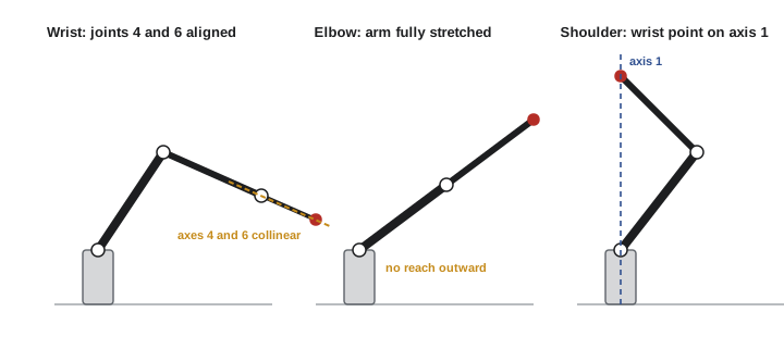
- Wrist singularity: the axes of joints 4 and 6 become collinear, which happens when joint 5 is at 0° (or 180°). Rotations of joints 4 and 6 then cancel, the wrist loses a degree of freedom, and the controller cannot tell how to split motion between them. This is the gimbal lock of lesson 3 appearing in hardware, and it is the most frequently encountered singularity in practice because it can occur anywhere in the workspace.
- Elbow singularity: the arm is fully stretched or folded, \( \theta_3 \) at the angle that makes the forearm collinear with the upper arm, exactly as for the planar 2R arm. It occurs at the boundary of the workspace.
- Shoulder singularity: the wrist center lies on the axis of joint 1. Then rotating the waist does not move the wrist center, and the waist angle is undefined in inverse kinematics, as noted in lesson 8.
Collaborative arms with offset wrists, such as the UR series, have their own singular sets, documented by their manufacturers: for example, when the wrist 2 joint is near 0° or 180°, or when the wrist point passes near the cylinder around the base axis. Their controllers detect approach to these regions and either slow down, stop with a protective message, or, for jogging, switch to joint-space motion.
Worked problem
Wrist singularity in practice
A welding robot must rotate its torch at a constant 30°/s about a vertical axis while the wrist joint 5 is at 2°. Why do joints 4 and 6 spin rapidly?
Show solution
- Near \( \theta_5 = 0 \), joints 4 and 6 rotate about nearly the same axis, and the third independent rotation direction is supplied only weakly.
- The joint speed needed to supply the weak direction scales roughly as \( 1/\sin\theta_5 \): \( 1/\sin 2^\circ \approx 29 \).
- A 30°/s demand in the weak direction becomes on the order of 870°/s at joints 4 and 6, rotating in opposite senses.
Answer: The required speeds exceed the joint limits, so the controller either slows the whole path drastically or stops. Path planners avoid such paths by tilting the tool slightly or choosing a different wrist configuration.
Manipulability
Being exactly at a singularity is rare, but being near one degrades performance gradually. Measures of manipulability quantify how close a configuration is to singular and how well the arm can move in every direction. The most widely used is Yoshikawa's manipulability index (1985):
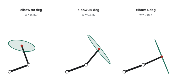
where \( \sigma_i \) are the singular values of J. It is zero at singularities and larger when the arm can move freely. For the 2R arm it equals \( L_1L_2|\sin\theta_2| \), maximized with the elbow bent at 90°. Humans unconsciously use this when writing or working at a bench: we hold our forearms at roughly right angles to the upper arm, where the arm is most maneuverable.
A richer picture comes from the manipulability ellipsoid. Joint velocities of unit size, \( \lVert \dot{\mathbf{q}} \rVert = 1 \), map through J to an ellipsoid of tool velocities. Its principal axes point along the left singular vectors of J and have lengths equal to the singular values. A round ellipsoid means the arm moves equally well in all directions; a long thin one means it moves easily in one direction and poorly in another; a flattened one means a singularity is near. The force ellipsoid, from \( J^\mathsf{T} \), is its inverse: directions in which the arm moves easily are directions in which it can exert only small forces for given joint torques, and vice versa.
Other useful measures are the condition number \( \kappa = \sigma_{\max}/\sigma_{\min} \), which is 1 for a perfectly isotropic arm and infinite at a singularity, and the smallest singular value \( \sigma_{\min} \) itself, which bounds the worst-case tool speed achievable with unit joint speeds. Because a pose Jacobian mixes meters and radians, its condition number depends on units; designers often divide the linear rows by a characteristic length to make the comparison fair.
import numpy as np
L1 = L2 = 0.5
def J2r(t1, t2):
    return np.array([[-L1*np.sin(t1) - L2*np.sin(t1+t2), -L2*np.sin(t1+t2)],
                     [ L1*np.cos(t1) + L2*np.cos(t1+t2),  L2*np.cos(t1+t2)]])
print(" elbow   w=sqrt(det JJ^T)  sigma_min  condition")
for deg in (90, 60, 30, 10, 2):
    J = J2r(0.0, np.radians(deg))
    s = np.linalg.svd(J, compute_uv=False)
    w = np.sqrt(np.linalg.det(J @ J.T))
print(f"{deg:5d} {w:12.4f} {s[-1]:8.4f} {s[0]/s[-1]:8.1f}") elbow w=sqrt(det JJ^T) sigma_min condition
90 0.2500 0.3090 2.6
60 0.2165 0.2220 4.4
30 0.1250 0.1156 9.4
10 0.0434 0.0390 28.6
2 0.0087 0.0078 143.2Workspace
The workspace is the set of positions the tool can reach. Two versions are distinguished. The reachable workspace contains every point the tool can reach with at least one orientation. The dexterous workspace, a subset, contains the points that can be reached with every orientation. For a planar 2R arm without joint limits, the reachable workspace is an annulus between radii \( |L_1 - L_2| \) and \( L_1 + L_2 \), and the dexterous workspace for a 3R arm with a tool length \( L_3 \) is the smaller annulus whose points stay reachable from every heading. Equal link lengths make the inner hole vanish, which is one reason many arms have upper arms and forearms of similar length.
Joint limits carve the ideal workspace into a smaller and often complicated shape. Manufacturers' data sheets show the working envelope as side and top views, with the reach usually stated as the distance from the base axis to the wrist center or flange at full extension. Planning a cell layout starts by checking that every target lies comfortably inside the envelope, not at its edge, where the arm is near the elbow singularity and cannot reorient the tool freely. A common rule of thumb is to keep regular targets within about 80 % of the maximum reach.
Worked problem
Is the target comfortably inside the envelope?
An arm has an upper arm of 0.425 m and a forearm of 0.392 m, measured to the wrist. A pick point puts the wrist center 0.78 m from the shoulder. Is that a good location?
Show solution
- Maximum reach: \( 0.425 + 0.392 = 0.817 \) m; minimum: \( 0.033 \) m.
- Ratio: \( 0.78/0.817 = 95\% \) of full reach.
- Elbow angle from the law of cosines: \( \cos\theta_3 = (0.78^2 - 0.425^2 - 0.392^2)/(2 \times 0.425 \times 0.392) = (0.6084 - 0.1806 - 0.1537)/0.3332 \approx 0.823 \), so \( \theta_3 \approx 34.6^\circ \).
Answer: Not ideal. At 95 % of reach the elbow is only about 35° from straight, manipulability is low and the tool cannot reorient much. Moving the robot or the pick point about 15 cm closer would put it near 80 % of reach.
| Concept | Definition | Design consequence |
|---|---|---|
| Reachable workspace | Points reachable with some orientation | Sets the cell size and robot placement |
| Dexterous workspace | Points reachable with every orientation | Where tools can be reoriented freely |
| Boundary singularity | Arm fully stretched or folded | Keep targets inside about 80 % of reach |
| Interior singularity | Axes align inside the workspace (wrist, shoulder) | Plan paths and tool tilts to avoid them |
| Manipulability w | \( \sqrt{\det JJ^\mathsf{T}} \) | Choose configurations and placements that keep it high |
| Condition number | \( \sigma_{\max}/\sigma_{\min} \) | Measures isotropy of motion and force |
Living with singularities
Singularities cannot be designed out of a serial arm; every arm with revolute joints has them. They can be managed. At design time, link lengths and joint offsets are chosen to keep singular sets away from the intended working region; some painting robots, for example, use non-spherical wrists that move the wrist singularity away from common orientations. At cell layout, the robot is placed so that typical targets lie in regions of high manipulability. At planning time, paths are checked for proximity to singularities using \( w \) or \( \sigma_{\min} \), and tool orientations with some freedom, such as a drill whose rotation about its own axis does not matter, are adjusted to avoid them. At run time, controllers use damped least squares (lesson 9), slow the path, or switch to joint interpolation near singularities. A redundant seventh joint, as on many collaborative and space arms, can steer around interior singularities altogether while the tool keeps moving.
Common mistakes
MistakePlacing frequently used targets at the edge of the working envelope.
InsteadKeep regular targets within about 80 % of maximum reach, away from the elbow singularity.
MistakePlanning straight-line moves through a wrist with joint 5 near zero.
InsteadCheck manipulability along Cartesian paths and tilt the tool or change configuration.
MistakeUsing the determinant's raw size to compare robots of different scale.
InsteadNormalize, or use the condition number or smallest singular value with consistent units.
MistakeAssuming singularities occur only at the workspace boundary.
InsteadWrist and shoulder singularities lie inside the workspace.
MistakeIgnoring force amplification near singularities.
InsteadNear singular configurations small joint torques can produce large contact forces; consider pinch risks.
Summary and key terms
- A singularity is a configuration where the Jacobian loses rank and some tool motion becomes impossible.
- For a 2R arm, \( \det J = L_1L_2\sin\theta_2 \): singular when stretched or folded.
- Near singularities, modest tool speeds demand very large joint speeds and forces can be amplified.
- Six-axis arms with spherical wrists have wrist, elbow and shoulder singularities.
- Manipulability \( w = \sqrt{\det JJ^\mathsf{T}} \), singular values and the condition number measure distance from singularity.
- Reachable and dexterous workspaces depend on link lengths and are reduced by joint limits.
- Singularities are managed through design, placement, path planning, damping and redundancy.
- Singularity
- A configuration where the Jacobian loses rank.
- Rank
- The number of independent columns or rows of a matrix.
- Boundary singularity
- A singularity at the edge of the workspace, with the arm stretched or folded.
- Interior singularity
- A singularity inside the workspace caused by aligned joint axes.
- Wrist singularity
- Alignment of the axes of joints 4 and 6, typically when joint 5 is at zero.
- Manipulability index
- Yoshikawa's measure \( \sqrt{\det JJ^\mathsf{T}} \) of how freely the tool can move.
- Manipulability ellipsoid
- The set of tool velocities produced by unit-norm joint velocities.
- Condition number
- The ratio of largest to smallest singular value.
- Reachable workspace
- All positions the tool can reach with at least one orientation.
- Dexterous workspace
- All positions the tool can reach with every orientation.
Practice problems
Work each problem on paper first, then reveal the answer to check.
For a 2R arm with \( L_1 = 0.4 \), \( L_2 = 0.3 \) m, what is det J at \( \theta_2 = 90^\circ \)?
Show answer
0.12 m².
At what elbow angles is a 2R arm singular?
Show answer
0° and 180°.
What is the manipulability of that arm at \( \theta_2 = 30^\circ \)?
Show answer
\( 0.12 \times 0.5 = 0.06 \) m².
Which singularity occurs when joint 5 of a spherical wrist is zero?
Show answer
The wrist singularity.
What is the reachable workspace of a 2R arm with \( L_1 = 0.5 \), \( L_2 = 0.3 \) m, with no limits?
Show answer
An annulus between 0.2 m and 0.8 m.
A Jacobian has singular values 0.9 and 0.03. What is its condition number?
Show answer
30.
Why do many arms use similar upper-arm and forearm lengths?
Show answer
To make the inner unreachable hole small.
A target is at 0.70 m and the maximum reach is 0.85 m. What fraction of reach is it?
Show answer
About 82 %.
Name two ways to avoid a wrist singularity on a path.
Show answer
Tilt the tool slightly, choose another wrist configuration or use joint interpolation for that segment.
What does a flattened manipulability ellipsoid indicate?
Show answer
The arm is near a singularity in the direction of the short axis.
Lesson quiz · 5 questions
Score 60% or more to complete this lesson.
Create a free account to save your progress, take quizzes and earn a certificate.