
ROB-200 · Lesson 3 of 12 · 28 min
Semiconductors: diodes, transistors and MOSFETs as switches
Resistors obey Ohm's law; semiconductors do not, and that is what makes them useful. A diode lets current flow one way only. A transistor lets a small signal control a large current. These two behaviors underlie every logic gate, every regulator, every motor driver and every microcontroller on a robot. This lesson treats them the way a robot builder uses them: as one-way valves and electrically controlled switches. You will learn to read the key datasheet numbers, choose a transistor to let a 3.3 V microcontroller pin switch a 12 V load, calculate the heat it produces and protect it from the inductive spikes that motors, relays and solenoids create.
How semiconductors conduct
Silicon in its pure form is a poor conductor. Adding tiny amounts of other elements, called doping, creates n-type silicon with spare electrons or p-type silicon with spare holes, places where an electron is missing that behave like positive charges. Where p-type and n-type regions meet, a pn junction forms, and the charges near the boundary rearrange into a thin depletion region that blocks current until an external voltage overcomes it. You do not need the solid-state physics to use these parts, but this picture explains why a silicon junction needs roughly 0.6 to 0.7 V before it conducts, and why that voltage falls by about 2 mV for every degree of temperature rise.
Diodes
A diode conducts when its anode is more positive than its cathode by the forward voltage, and blocks current in the other direction until the reverse voltage exceeds its breakdown rating. To a first approximation, a conducting diode drops a fixed voltage: about 0.7 V for a silicon rectifier, 0.2 to 0.45 V for a Schottky diode, and 1.8 to 3.3 V for light-emitting diodes, depending on color. Datasheets give the maximum forward current, the maximum reverse voltage and the forward voltage at a stated current.
| Diode type | Typical forward voltage | Common robot uses |
|---|---|---|
| Silicon rectifier (e.g. 1N4007 family) | 0.7 to 1.0 V | Reverse-polarity protection, rectifying chargers |
| Small-signal (e.g. 1N4148 family) | 0.6 to 0.7 V at low current | Logic protection, small flyback diodes |
| Schottky | 0.2 to 0.45 V | Flyback diodes for motors, power OR-ing, switching regulators |
| Zener | Reverse breakdown at a set voltage (e.g. 3.3 V, 5.1 V) | Simple clamps and voltage references |
| TVS (transient voltage suppressor) | Clamps fast surges | Protecting inputs, CAN lines and power rails from spikes |
| LED | 1.8 V red to about 3.2 V blue or white | Indicators, lighting, optical sensors |
Diodes protect circuits in several ways. A diode in series with the battery input blocks current if the battery is connected backwards, at the cost of its forward drop and the heat that drop produces at high current. Clamp diodes from an input pin to the supply and ground rails, built into most microcontrollers, conduct if the input goes outside the rails, so modest overvoltages are absorbed rather than destroying the chip, provided a series resistor limits the current. A TVS diode across a supply or communication line clamps short, high-energy surges, such as those from electrostatic discharge.
Bipolar junction transistors
A bipolar junction transistor (BJT) has three terminals: base, collector and emitter. In an NPN transistor, a small current flowing into the base and out of the emitter allows a much larger current to flow from collector to emitter. The ratio is the current gain, written β or hFE, typically 50 to 300 for small transistors. The base-emitter junction is a diode, so the base sits about 0.7 V above the emitter when the transistor is on.
Used as a switch, a BJT is driven hard into saturation, where the collector-emitter voltage falls to about 0.1 to 0.3 V and the transistor acts like a closed switch. To make sure it saturates, designers supply about ten times the base current the gain alone would require. BJTs are inexpensive and work well for switching up to a few hundred milliamperes: LEDs, small relays, buzzers. For larger currents, the base current a microcontroller would need to supply becomes impractical, and MOSFETs take over.
Worked problem
Sizing a base resistor
An NPN transistor with a minimum gain of 100 switches a 12 V relay coil that draws 80 mA. A 3.3 V microcontroller pin drives the base. Choose the base resistor.
Show solution
- Base current needed for the gain alone: \( 80 / 100 = 0.8 \) mA. For solid saturation use about 10 times that minimum ratio, a forced gain of 10: \( I_B = 8 \) mA, which is high for a pin, so compromise at a forced gain of 20: \( I_B = 4 \) mA.
- Voltage across the resistor: \( 3.3 - 0.7 = 2.6 \) V.
- \( R_B = 2.6 / 0.004 = 650\ \Omega \); use the standard 680 Ω, giving about 3.8 mA.
- Check the pin can source 3.8 mA; most microcontroller pins can supply 4 to 12 mA, but read the datasheet.
Answer: About 680 Ω. The relay coil also needs a flyback diode, as explained below.
MOSFETs
A metal-oxide-semiconductor field-effect transistor (MOSFET) is controlled by voltage rather than current. Its gate is insulated from the channel by a thin oxide layer, so in steady state no gate current flows. Applying a voltage between gate and source above the threshold voltage creates a conducting channel between drain and source. When fully on, the channel behaves like a small resistor, RDS(on), which for a good power MOSFET can be a few milliohms. An N-channel MOSFET placed between the load and ground, called a low-side switch, is the workhorse for switching motors, solenoids, LED strips and heaters from a microcontroller.
Three datasheet values matter most. The drain-source voltage rating must exceed the supply plus any spikes, with margin. The continuous drain current rating, which assumes ideal cooling, gives an upper bound but rarely the real limit. And RDS(on) must be read at the gate voltage you will actually apply. A trap catches many beginners here: the threshold voltage, often 1 to 2.5 V, is where the MOSFET only begins to conduct, not where it is fully on. Many power MOSFETs specify RDS(on) only at a 10 V gate drive. Driven from a 3.3 V pin, they may be only partly on, with high resistance and serious heating. Choose a logic-level MOSFET with RDS(on) specified at 2.5 V or 4.5 V, or use a gate driver chip that provides 10 V or more.
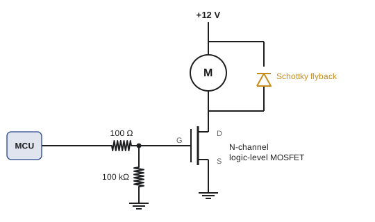
Two small resistors complete the circuit. A gate resistor of about 10 to 100 Ω limits the brief current that charges the gate capacitance and damps ringing. A pull-down resistor of about 10 to 100 kΩ from gate to source holds the MOSFET off when the microcontroller pin is floating, as it is during reset and boot. Without it, a motor might twitch every time the robot powers up, which is alarming at best and dangerous at worst.
Power dissipation and heat
A switch that is fully on dissipates power in its on-resistance; a switch that is fully off dissipates almost nothing. In between, during switching, the MOSFET briefly carries current with voltage across it, and that switching loss grows with frequency. For on-off control at low frequency, conduction loss dominates:
The second formula estimates the junction temperature from the ambient temperature and the thermal resistance from junction to ambient, \( R_{\theta JA} \), in degrees per watt, given in the datasheet for a stated mounting. Silicon junctions are usually rated to 150 or 175 °C, but good designs stay well below, at perhaps 100 to 125 °C, because lifetime falls as temperature rises. RDS(on) itself rises with temperature, by roughly 1.5 to 2 times between 25 °C and 150 °C, so a hot MOSFET dissipates more and gets hotter still. Always calculate with the hot value.
Worked problem
Will the MOSFET overheat?
A logic-level MOSFET with RDS(on) = 12 mΩ at 4.5 V gate drive (rising to about 18 mΩ when hot) switches a 10 A heater. In its package on a typical board, RθJA is 50 °C/W. The robot's enclosure reaches 45 °C. Is it safe?
Show solution
- Using the hot resistance: \( P = 10^2 \times 0.018 = 1.8 \) W.
- \( T_J = 45 + 1.8 \times 50 = 135\ ^\circ\text{C} \).
- That is below a 150 °C or 175 °C absolute maximum but above a sensible design target of about 110 °C.
- Options: a MOSFET with lower RDS(on), more copper area or a heatsink to reduce RθJA, or two MOSFETs in parallel, which halves the resistance and quarters the loss in each.
Answer: Marginal: about 135 °C. Improve the cooling or choose a lower-resistance part.
def junction_temp(i, rds_on, r_theta_ja, t_ambient):
    p = i**2 * rds_on
    return p, t_ambient + p * r_theta_ja

for label, rds, rth in [("12 mOhm, small pad", 0.018, 50),
                        ("12 mOhm, large copper", 0.018, 30),
                        ("4 mOhm, large copper", 0.006, 30)]:
    p, tj = junction_temp(10, rds, rth, 45)
print(f"{label:22s} P = {p:4.2f} W Tj = {tj:5.1f} C")12 mOhm, small pad P = 1.80 W Tj = 135.0 C 12 mOhm, large copper P = 1.80 W Tj = 99.0 C 4 mOhm, large copper P = 0.60 W Tj = 63.0 C
Inductive loads and flyback
Motors, relays and solenoids contain coils, and a coil resists changes in its current. The voltage across an inductor is proportional to how fast its current changes:
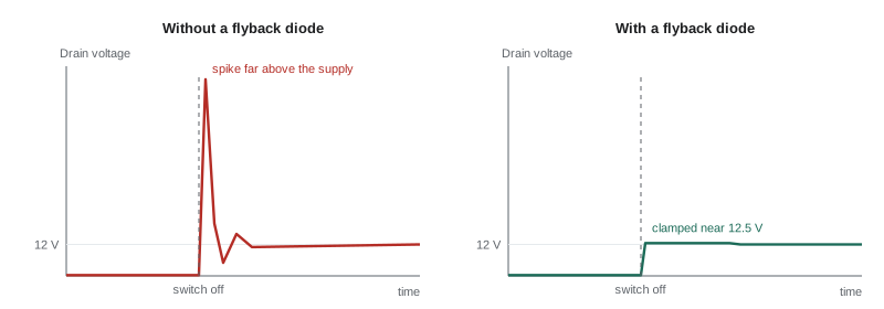
When a switch turns off and tries to stop the current suddenly, dI/dt becomes enormous and the coil produces a voltage spike, often hundreds of volts, that can destroy the transistor in a single event. A flyback diode, also called a freewheeling diode, placed across the coil with its cathode toward the positive supply, gives the current a path to circulate and decay safely. Schottky diodes are preferred for motors because they turn on quickly. The diode slows the release of relays slightly; where fast release matters, a Zener or TVS diode in series with it lets the coil voltage rise to a higher but controlled level. Lesson 11 extends this to H-bridges, where the MOSFETs' own internal body diodes play the same role.
High-side switching
Low-side switches are simple but leave the load connected to the positive supply, which can matter when the load's ground must stay connected, as with a sensor or a module that communicates with the microcontroller. A high-side switch sits between the supply and the load. A P-channel MOSFET can do this: its gate is pulled to the supply to turn it off and pulled lower to turn it on, usually through a small NPN or N-channel transistor because the microcontroller pin cannot reach the supply voltage. P-channel parts have higher RDS(on) than equivalent N-channel ones. For high currents, designers use N-channel MOSFETs on the high side with a gate driver that produces a voltage above the supply, using a bootstrap capacitor or charge pump. Integrated high-side switch chips, common in vehicles, add current limiting and diagnostics in one package.
| Switch | Best for | Watch out for |
|---|---|---|
| NPN BJT, low side | LEDs, buzzers, small relays below about 300 mA | Base current from the pin; saturation voltage |
| N-channel MOSFET, low side | Motors, solenoids, heaters, LED strips | Logic-level gate rating; load stays tied to supply |
| P-channel MOSFET, high side | Switching power to modules and sensors | Higher RDS(on); gate must swing to the supply |
| N-channel with gate driver, high side | High-current loads and H-bridges | Needs bootstrap or charge pump |
| Solid-state relay or load switch IC | Isolated or protected switching | Cost; leakage when off |
Common mistakes
MistakeChoosing a MOSFET by its threshold voltage and driving it from 3.3 V.
InsteadCheck RDS(on) at the gate voltage you will actually apply, or use a gate driver.
MistakeLeaving the MOSFET gate floating during boot.
InsteadAdd a pull-down resistor from gate to source.
MistakeSwitching a motor, relay or solenoid without a flyback path.
InsteadAdd a fast diode across the coil, or use a driver with built-in protection.
MistakeCalculating heat with the room-temperature RDS(on).
InsteadUse the hot value and the RθJA for your actual board layout.
MistakeDriving a BJT with just enough base current for the typical gain.
InsteadOverdrive the base so the transistor saturates even with the minimum gain.
Summary and key terms
- A diode conducts one way with a roughly fixed forward drop: about 0.7 V silicon, 0.3 V Schottky, 2 to 3 V LEDs.
- Diodes protect against reverse polarity, overvoltage on inputs and surges (TVS).
- A saturated BJT switches small loads; size the base resistor with a forced gain of 10 to 20.
- An N-channel MOSFET on the low side switches large loads with no steady gate current; check RDS(on) at your gate voltage.
- Conduction loss is I²RDS(on); junction temperature is ambient plus power times thermal resistance.
- Inductive loads produce voltage spikes when switched off; a flyback diode clamps them.
- High-side switching uses P-channel MOSFETs, or N-channel MOSFETs with a gate driver.
- pn junction
- The boundary between p-type and n-type semiconductor that conducts in one direction.
- Forward voltage
- The voltage across a diode when it conducts.
- Schottky diode
- A diode with a low forward voltage and fast switching.
- Current gain (β)
- The ratio of collector current to base current in a BJT.
- Saturation
- The fully on state of a BJT switch, with a small collector-emitter voltage.
- Threshold voltage
- The gate-source voltage at which a MOSFET begins to conduct.
- RDS(on)
- The drain-source resistance of a fully on MOSFET at a stated gate voltage.
- Logic-level MOSFET
- A MOSFET specified to turn fully on at low gate voltages such as 2.5 V or 4.5 V.
- Thermal resistance
- Temperature rise per watt between two points, such as junction and ambient.
- Flyback diode
- A diode across an inductive load that gives its current a path when the switch opens.
Practice problems
Work each problem on paper first, then reveal the answer to check.
A 9 V supply feeds a red LED (2.0 V) through a series silicon diode (0.7 V) for polarity protection. What resistor sets 10 mA?
Show answer
(9 − 2.0 − 0.7)/0.010 = 630 Ω; use 620 or 680 Ω.
A BJT with minimum gain 50 must switch 150 mA. With a forced gain of 15, what base current is needed?
Show answer
10 mA, more than many pins can supply, so use a MOSFET instead.
A MOSFET with 25 mΩ hot RDS(on) carries 6 A. What is the conduction loss?
Show answer
0.9 W.
With RθJA = 62 °C/W and 40 °C ambient, what is the junction temperature for 0.9 W?
Show answer
About 96 °C.
Why does a MOSFET gate need a pull-down resistor?
Show answer
To keep it off while the driving pin floats during reset and boot.
Which way round does a flyback diode go?
Show answer
Across the coil, cathode to the positive supply, so it does not conduct in normal operation.
What does a TVS diode do on a CAN line?
Show answer
Clamps electrostatic discharge and surges to a safe voltage.
Why are two MOSFETs in parallel cooler than one?
Show answer
Each carries half the current, so each dissipates a quarter of the original loss.
A MOSFET datasheet lists RDS(on) only at VGS = 10 V. Is it suitable for a 3.3 V microcontroller pin directly?
Show answer
Probably not; it may be only partly on. Use a logic-level part or a gate driver.
What is one advantage of high-side switching?
Show answer
The load keeps its ground connection, which matters for modules that communicate with the controller.
Lesson quiz · 5 questions
Score 60% or more to complete this lesson.
Create a free account to save your progress, take quizzes and earn a certificate.