
ROB-200 · Lesson 1 of 12 · 30 min
Circuits for roboticists: voltage, current and power
Every robot is, underneath its software, an electrical machine. Batteries store energy, wires and circuit boards carry it, sensors turn physical quantities into voltages, microcontrollers read and produce logic signals, and motor drivers turn small control signals into large currents that move wheels and joints. A roboticist who understands only the software is at the mercy of mysterious resets, sensors that read nonsense, boards that get hot and motors that stutter. This course gives you the working electronics you need to build, connect and debug the hardware layer of a robot. It starts here with the ideas everything else rests on: charge, voltage, current, resistance and power, and the two laws that let you analyze almost any simple circuit.
You met electric charge, fields and potential in PHYS-130. This lesson takes a practical view. We will treat circuits as networks of ideal parts, calculate what currents flow and how much power each part dissipates, and learn the habits that keep both you and your hardware safe. The maths is algebra; the skill is knowing which formula answers the question in front of you.
Voltage, current and resistance
Voltage is the difference in electrical potential energy per unit charge between two points, measured in volts (V). It is always measured between two points, which is why every circuit needs a reference, usually called ground and marked 0 V. When a datasheet says a pin is at 3.3 V, it means 3.3 V above the board's ground. Current is the rate at which charge flows past a point, measured in amperes (A); one ampere is one coulomb per second. In robot electronics you will see everything from microamperes drawn by a sleeping microcontroller to tens of amperes drawn by a stalled drive motor.
By convention, current flows from higher to lower potential, from the positive terminal of a source, through the circuit, and back to the negative terminal. Physically, electrons in metal wires drift the other way, but every schematic, datasheet and textbook uses conventional current, and so will we. The key rule is that current flows only around a closed loop. An open switch, a broken wire or a cracked solder joint stops it everywhere in that loop, which is why intermittent connections are among the most frustrating faults in robotics.
Resistance, measured in ohms (Ω), describes how strongly a component opposes current. For many materials and components over a useful range, the current is proportional to the voltage across them, a relationship called Ohm's law:
Resistors are components made to have a stated resistance, with a tolerance such as ±1 % or ±5 %. They are used to limit current, divide voltages, pull signal lines to a known level and sense current. Wires and circuit board traces also have resistance, small but not zero, and that matters when currents are large. A copper trace that drops 0.1 V at 10 mA drops 100 times as much at 1 A, which is enough to upset a sensor that shares the same ground return.
| Quantity | Symbol | Unit | Typical values in a small robot |
|---|---|---|---|
| Voltage | V | volt (V) | 3.3 V logic, 5 V USB, 7.4 to 24 V battery |
| Current | I | ampere (A) | 20 µA sleep, 50 mA microcontroller, 2 to 30 A motors |
| Resistance | R | ohm (Ω) | 10 Ω to 1 MΩ resistors, milliohms for wires and sense resistors |
| Power | P | watt (W) | 0.1 W for logic, 10 to 500 W for drive motors |
| Energy | E | joule (J) or watt-hour (Wh) | 20 to 500 Wh battery packs |
| Charge | Q | coulomb (C) or ampere-hour (Ah) | 2 to 20 Ah battery capacity |
Series and parallel
Components connected end to end, so that the same current passes through each, are in series. Their resistances add. Components connected across the same two points, so that each has the same voltage across it, are in parallel. For parallel resistors, the conductances (the reciprocals of resistance) add, so the combined resistance is always smaller than the smallest branch:
For two resistors in parallel this simplifies to the product over the sum, \( R_1 R_2 / (R_1 + R_2) \). Two equal resistors in parallel give half the value of one. In a robot, the loads on a battery are mostly in parallel: the microcontroller, the sensors and each motor driver are all connected across the same supply, and each draws the current it needs. Adding a load in parallel increases the total current from the battery but, ideally, does not change the voltage the other loads see. In practice it does, a little, because the battery and the wiring have internal resistance, which is one reason motor starts can brown out a poorly designed logic supply.
Kirchhoff's laws
Two conservation laws, published by Gustav Kirchhoff in 1845, let you analyze circuits too complicated for series and parallel rules alone. Kirchhoff's current law (KCL) says the currents flowing into any node, a point where conductors meet, sum to zero: charge does not pile up. Kirchhoff's voltage law (KVL) says the voltages around any closed loop sum to zero: if you walk around a loop and return to where you started, you are back at the same potential.
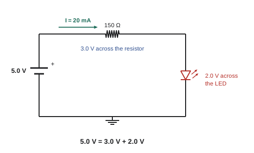
KCL is how you budget current. If a 12 V battery feeds a motor driver drawing 4 A, a 5 V regulator drawing 0.6 A and a lidar drawing 0.7 A, the battery supplies 5.3 A, and the fuse, connector and wire must all be rated for it. KVL is how you find voltages. In a loop of a 5 V supply, a resistor and an LED, the supply voltage must equal the resistor voltage plus the LED voltage, which is exactly the calculation you do to choose an LED resistor.
Worked problem
Choosing an LED resistor
A status LED on a robot has a forward voltage of 2.0 V and should run at 20 mA from a 5 V supply. What resistor is needed, and how much power does it dissipate?
Show solution
- By KVL, the resistor drops \( 5.0 - 2.0 = 3.0 \) V.
- By Ohm\'s law, \( R = 3.0 / 0.020 = 150\ \Omega \).
- Power in the resistor: \( P = V I = 3.0 \times 0.020 = 0.060 \) W, or 60 mW.
- A standard 1/8 W (125 mW) or 1/4 W resistor has plenty of margin. 150 Ω is a standard value in the E12 series, so no rounding is needed.
Answer: 150 Ω, dissipating 60 mW. Indicator LEDs today are bright enough that 2 to 5 mA is usually plenty, which would allow 600 Ω to 1.5 kΩ and save power.
Calculations like these are quick to automate. The listing below finds the ideal LED resistor for several supply voltages and rounds each up to the next standard E12 value, so the current never exceeds the target.
E12 = [1.0, 1.2, 1.5, 1.8, 2.2, 2.7, 3.3, 3.9, 4.7, 5.6, 6.8, 8.2]

def next_e12(r):
    """Smallest standard E12 resistor value >= r (ohms)."""
    decade = 1.0
    while True:
        for base in E12:
            if base * decade >= r - 1e-9:
                return base * decade
        decade *= 10

vf, i_target = 2.0, 0.020          # LED forward voltage (V), current (A)
for vs in (3.3, 5.0, 12.0, 24.0):
    r_ideal = (vs - vf) / i_target
    r = next_e12(r_ideal)
    i = (vs - vf) / r
    p = i**2 * r
    print(f"{vs:5.1f} V: ideal {r_ideal:6.0f} ohm -> use {r:6.0f} ohm, "
f"{i*1000:4.1f} mA, {p*1000:5.0f} mW")3.3 V: ideal 65 ohm -> use 68 ohm, 19.1 mA, 25 mW 5.0 V: ideal 150 ohm -> use 150 ohm, 20.0 mA, 60 mW 12.0 V: ideal 500 ohm -> use 560 ohm, 17.9 mA, 179 mW 24.0 V: ideal 1100 ohm -> use 1200 ohm, 18.3 mA, 403 mW
Look at the 24 V line. The resistor dissipates far more power than the LED, about 400 mW, which needs at least a 1/2 W part and wastes energy. At high supply voltages, designers drive indicators at lower currents or use a constant-current driver instead. The same reasoning, budgeting the voltage drop across each part and checking its power, applies to every circuit in this course.
The voltage divider
Two resistors in series across a voltage form a voltage divider. The same current flows through both, so the voltage splits in proportion to the resistances. The output, taken across the lower resistor, is:
Voltage dividers are everywhere in robots. They scale a battery voltage down to a range the microcontroller's analog-to-digital converter can read, they set the output of adjustable regulators, and a potentiometer, a resistor with a sliding contact, is a divider whose ratio you set by turning a knob, which makes it the classic joint-angle sensor in hobby servos. The formula assumes no current is drawn from the output. If the load connected to the output has a resistance comparable to R2, it is effectively in parallel with R2 and pulls the output down, so a divider is a signal source, never a power supply.
Worked problem
Reading a battery voltage
A robot's 4-cell lithium-ion pack ranges from 12.0 V empty to 16.8 V full. The microcontroller's ADC accepts 0 to 3.3 V. Design a divider with a little margin.
Show solution
- Aim for about 3.0 V at 16.8 V, a ratio of \( 3.0 / 16.8 \approx 0.179 \).
- Choose \( R_2 = 10\ \text{k}\Omega \). Then \( R_1 + R_2 = 10 / 0.179 \approx 56 \) kΩ, so \( R_1 \approx 46 \) kΩ; use the standard 47 kΩ.
- Check: \( 16.8 \times 10 / 57 \approx 2.95 \) V at full charge and \( 12.0 \times 10/57 \approx 2.11 \) V empty, both safely inside the range.
- The divider draws \( 16.8 / 57\,000 \approx 0.29 \) mA continuously, about 7 Ah per year, acceptable for a robot that is charged weekly but not for one stored for months; a MOSFET switch can disconnect it.
Answer: R1 = 47 kΩ and R2 = 10 kΩ give 2.1 to 3.0 V. Add a small capacitor across R2 to filter noise, as lesson 8 explains.
Power and energy
Power is the rate of energy transfer, measured in watts. In any component the power is the voltage across it multiplied by the current through it. Combining with Ohm's law gives two more forms that are useful for resistors:
The \( I^2 R \) form explains why high currents are expensive. Doubling the current through a wire quadruples the heat produced in it. A 2 m pair of wires with 20 mΩ total resistance wastes only 0.02 W at 1 A but 8 W at 20 A, and drops 0.4 V, which is one reason drive systems in larger robots use 24 or 48 V rather than 12 V: for the same power, higher voltage means lower current and much lower wiring losses. Every watt dissipated in a component becomes heat, and each component has a power rating beyond which it overheats. Exceeding ratings is the most common way beginners destroy parts.
Energy is power integrated over time. Electricity bills use kilowatt-hours; robot batteries are rated in watt-hours or in ampere-hours at a nominal voltage. A 14.4 V, 5 Ah pack stores about 72 Wh. A robot drawing an average of 36 W would run for about two hours, less in practice, as the next lesson shows.
Direct and alternating current, and ground
Almost everything inside a mobile robot runs on direct current (DC), steady in direction, from batteries or from power supplies that convert mains alternating current (AC) to DC. Mains AC is 120 V at 60 Hz in both Canada and the United States, and it is dangerous: currents of tens of milliamperes through the body can disturb the heart. This course deals with low-voltage DC circuits, typically below 50 V, which are far safer to touch but still able to deliver enormous currents from a lithium battery and start fires.
Ground deserves special attention. On a schematic, the ground symbol means all those points are connected and form the 0 V reference. On a real robot, ground is a set of wires and copper planes with resistance, carrying the return current of every load. If a 10 A motor return and a sensitive sensor share the same thin ground wire, the motor current creates a voltage drop that appears as noise in the sensor's reading. Good practice keeps high-current returns separate from signal grounds and joins them at a single point near the battery, a technique called star grounding, which lesson 12 revisits.
Safety and the code
Low-voltage robot electronics are not usually wired into a building, but anything that plugs into the mains, such as a charger or a bench supply, should be listed by a Nationally Recognized Testing Laboratory (NRTL), such as UL, CSA or Intertek (ETL); OSHA requires listed equipment in workplaces. Installations follow the National Electrical Code (NFPA 70, 2026 edition), adopted by states and cities on their own schedules, and OSHA's electrical standards and NFPA 70E govern work on energized equipment. Your robot projects should use listed chargers and supplies and keep anything over 50 V, including mains, enclosed and out of reach.
Three habits prevent most accidents with low-voltage hardware. First, disconnect power before changing wiring; a probe slipping between two pins of a live board can destroy it instantly. Second, fuse every battery as close to its terminal as possible, so a short circuit anywhere downstream blows the fuse rather than melting a wire. Third, never trust a single measurement or assumption: before applying power to a new board, check the supply for shorts with a multimeter and power it from a current-limited bench supply first, so a mistake costs a few milliamperes rather than a component.
Common mistakes
MistakeMeasuring a voltage "at a pin" without thinking about the reference point.
InsteadVoltage is always between two points; know which ground your meter and your circuit use.
MistakeConnecting an LED directly to a 5 V supply or a microcontroller pin.
InsteadAlways limit LED current with a resistor or a constant-current driver.
MistakeUsing a voltage divider to power a sensor or module.
InsteadDividers are only for signals with negligible load current; use a regulator for power.
MistakeChoosing wire and connectors by voltage alone.
InsteadSize conductors and connectors for the current, and check the voltage drop with Ohm's law.
MistakeRunning motor return current through the same thin ground wire as sensors.
InsteadKeep high-current returns separate and join grounds at a single point.
Summary and key terms
- Voltage is a potential difference between two points; current is the flow of charge around a closed loop.
- Ohm's law, V = IR, relates voltage, current and resistance for resistive parts.
- Series resistances add; parallel resistances combine through their reciprocals and give a smaller total.
- KCL: currents into a node sum to zero. KVL: voltages around a loop sum to zero.
- A voltage divider gives Vout = Vin R2/(R1 + R2) when the output is lightly loaded.
- Power is P = VI = I²R = V²/R; high currents waste power and drop voltage in wiring.
- Use certified chargers, fuse batteries, power new boards from a current-limited supply and plan grounds carefully.
- Voltage
- The difference in electrical potential between two points, in volts.
- Current
- The rate of flow of electric charge, in amperes.
- Resistance
- Opposition to current, in ohms; the ratio of voltage to current for a resistor.
- Ohm's law
- V = IR, the proportional relationship between voltage and current in a resistor.
- Node
- A point in a circuit where two or more conductors meet.
- Kirchhoff's current law
- The sum of currents entering a node equals the sum leaving it.
- Kirchhoff's voltage law
- The sum of voltages around any closed loop is zero.
- Voltage divider
- Two series resistors whose junction gives a fixed fraction of the input voltage.
- Ground
- The circuit's 0 V reference and the common return path for current.
- Star grounding
- Joining separate ground returns at a single point to stop currents sharing conductors.
Practice problems
Work each problem on paper first, then reveal the answer to check.
A 3.3 V pin drives an LED with a 1.8 V forward voltage through a 330 Ω resistor. What is the current?
Show answer
(3.3 − 1.8)/330 ≈ 4.5 mA.
What is the resistance of 220 Ω and 330 Ω in series, and in parallel?
Show answer
Series 550 Ω; parallel 220 × 330 / 550 = 132 Ω.
A node has 2.0 A entering and two branches leaving; one carries 0.7 A. What does the other carry?
Show answer
1.3 A, by KCL.
A divider has R1 = 20 kΩ and R2 = 10 kΩ across 9 V. What is Vout?
Show answer
9 × 10/30 = 3.0 V.
A 4.7 Ω resistor carries 0.5 A. What power does it dissipate?
Show answer
0.5² × 4.7 ≈ 1.18 W, so it needs at least a 2 W rating.
A motor draws 15 A through wiring with 30 mΩ total resistance. What voltage is lost and what power wasted?
Show answer
0.45 V and 6.75 W.
A 25.2 V, 4 Ah pack stores how many watt-hours?
Show answer
About 100.8 Wh.
Why does a voltage divider's output fall when you connect a load?
Show answer
The load is in parallel with R2, lowering the effective lower resistance and therefore the ratio.
A 12 V battery feeds loads of 2.5 A, 0.8 A and 1.2 A. What current must the main fuse and wire carry continuously?
Show answer
4.5 A, plus margin; choose the fuse above normal load but below the wire's rating.
Why do larger robots favor 48 V drive systems over 12 V?
Show answer
For the same power the current is a quarter, so I²R wiring losses fall to one sixteenth and connectors and wires can be smaller.
Lesson quiz · 5 questions
Score 60% or more to complete this lesson.
Create a free account to save your progress, take quizzes and earn a certificate.