
ROB-200 · Lesson 2 of 12 · 31 min
Batteries and robot power systems
A mobile robot carries its energy with it, and the battery is often the heaviest, most expensive and most dangerous part on board. How long the robot runs, how hard it can accelerate, whether its computer resets when the motors start and whether it can be shipped by air all depend on the battery and the power system built around it. This lesson covers the battery chemistries robots use, how capacity, C-rate and internal resistance determine performance, the battery management systems that keep lithium cells safe, the regulators that turn one battery voltage into the several rails a robot needs, and the fuses, switches and transport rules that complete a safe power system.
Cells, packs and chemistries
A cell is a single electrochemical unit with a voltage set by its chemistry. A battery or pack is several cells connected in series to raise the voltage and in parallel to raise the capacity. Pack configurations are written as, for example, 4S2P: four cells in series, two in parallel, eight cells in all. The series count sets the voltage; the parallel count multiplies the capacity and the current the pack can deliver.
| Chemistry | Nominal cell voltage | Full / empty | Specific energy | Typical robot use |
|---|---|---|---|---|
| Lithium-ion (NMC, NCA) | 3.6 to 3.7 V | 4.2 V / about 3.0 V | 150 to 270 Wh/kg | Most mobile robots, drones, humanoids |
| Lithium polymer (LiPo) | 3.7 V | 4.2 V / 3.3 to 3.5 V | 130 to 200 Wh/kg | High-discharge hobby robots and drones |
| Lithium iron phosphate (LFP) | 3.2 V | 3.65 V / 2.5 V | 90 to 160 Wh/kg | Industrial AMRs, long cycle life, safer |
| Nickel-metal hydride (NiMH) | 1.2 V | 1.4 V / 1.0 V | 60 to 120 Wh/kg | Toys, education kits, legacy robots |
| Sealed lead-acid (SLA) | 2.0 V | 2.1 V / 1.75 V | 30 to 40 Wh/kg | Heavy, cheap; older carts and wheelchairs |
Lithium chemistries dominate because they store far more energy per kilogram. A 4S lithium-ion pack has a nominal voltage of about 14.4 V and swings from 16.8 V full to about 12 V empty, a range every circuit on the robot must tolerate. LFP cells store less energy but survive thousands of cycles and are much less prone to thermal runaway, which is why many warehouse robots that run around the clock use them. Lithium polymer is lithium-ion in a soft pouch rather than a metal can; it can be made thin and can deliver very high currents, but the pouch offers little mechanical protection.
Capacity, energy and runtime
Capacity is the charge a battery can deliver, in ampere-hours (Ah) or milliampere-hours (mAh). Energy is capacity multiplied by the nominal voltage, in watt-hours. Comparing packs of different voltages by mAh is misleading; compare watt-hours. To estimate runtime, divide usable energy by average power, then derate, because you should not drain lithium cells completely, capacity falls in the cold and with age, and conversion losses in regulators and motor drivers add up.
Worked problem
Estimating runtime
A delivery robot uses a 7S4P pack of 3.6 V, 3.0 Ah cells. Its average load is 120 W. Allow 80 % usable depth of discharge and 90 % efficiency in the power electronics. How long will it run?
Show solution
- Pack voltage: \( 7 \times 3.6 = 25.2 \) V nominal. Capacity: \( 4 \times 3.0 = 12 \) Ah.
- Energy: \( 25.2 \times 12 = 302 \) Wh.
- Usable after derating: \( 302 \times 0.80 \times 0.90 \approx 218 \) Wh.
- Runtime: \( 218 / 120 \approx 1.8 \) h, or about 109 minutes.
Answer: About 1.8 hours. In winter, or after a few hundred cycles, plan for less, perhaps 1.4 hours.
The listing below automates the same estimate and shows how runtime changes with load. Writing it as a function makes it easy to explore design choices, such as adding a parallel string or reducing the computer's power draw.
def runtime_h(series, parallel, cell_v, cell_ah, load_w,
              usable=0.80, efficiency=0.90):
    energy_wh = series * cell_v * parallel * cell_ah
    return energy_wh * usable * efficiency / load_w

pack = dict(series=7, parallel=4, cell_v=3.6, cell_ah=3.0)
for load in (80, 120, 200, 300):
    print(f"{load:4d} W average -> {runtime_h(**pack, load_w=load):4.2f} h")
print(f"7S5P at 120 W -> {runtime_h(7, 5, 3.6, 3.0, 120):4.2f} h")80 W average -> 2.72 h 120 W average -> 1.81 h 200 W average -> 1.09 h 300 W average -> 0.73 h 7S5P at 120 W -> 2.27 h
C-rate and internal resistance
The C-rate expresses current relative to capacity: 1C for a 5 Ah pack is 5 A, 2C is 10 A, 0.5C is 2.5 A. Cell datasheets give a maximum continuous discharge rate and often a higher short-pulse rate, plus a maximum charge rate, commonly 0.5C to 1C for lithium-ion. A robot's peak current, during acceleration or when a motor stalls, must stay within the pack's rating, which is one reason designers add parallel strings even when capacity alone would be enough.
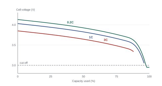
Every cell has internal resistance, typically 15 to 50 mΩ for an 18650-size cell and much less for large pouch cells. When the pack delivers current, its terminal voltage sags by \( I R_{\text{int}} \), and the cell heats by \( I^2 R_{\text{int}} \). For a pack, the internal resistance is the cell resistance multiplied by the series count and divided by the parallel count. Voltage sag is why a robot's computer can reset when motors start: if the battery dips below what a regulator needs, the logic supply collapses for a few milliseconds, which is enough to reboot a microcontroller.
Worked problem
Voltage sag at peak current
The 7S4P pack above uses cells with 40 mΩ internal resistance. Two drive motors draw 30 A together when accelerating from a standstill. How far does the pack voltage sag, and what is the C-rate?
Show solution
- Pack resistance: \( 40 \times 7 / 4 = 70 \) mΩ.
- Sag: \( 30 \times 0.070 = 2.1 \) V.
- Near empty the open-circuit voltage is about \( 7 \times 3.2 = 22.4 \) V, so the terminal voltage dips to about 20.3 V.
- C-rate: \( 30 / 12 = 2.5\text{C} \), within the 3C continuous rating typical of power cells but above what high-energy cells allow.
Answer: About 2.1 V of sag at 2.5C. Any regulator on the robot must keep working down to about 20 V, plus margin.
Battery management systems
Lithium cells are unforgiving. Charging above about 4.2 V per cell, discharging too deeply, charging below freezing, or overheating can damage them, and in the worst case trigger thermal runaway: an internal short heats the cell, the heat drives reactions that produce more heat and flammable gas, and the cell vents and can ignite its neighbors. A battery management system (BMS) prevents this. A BMS monitors every series cell group's voltage, the pack current and temperatures, disconnects the pack with MOSFET switches if any limit is exceeded, and balances the cells by bleeding a little charge from the highest groups so they stay matched over many cycles.
Smart packs also estimate state of charge, the percentage of capacity remaining, by counting charge in and out (coulomb counting) and correcting with the voltage at rest, and report it to the robot over a serial bus such as SMBus or CAN. That lets the robot return to its charger in time, which matters more than any other feature for an autonomous robot. Battery cells themselves should be certified to safety standards such as IEC 62133-2 and the UN 38.3 transport tests, and robot and e-mobility packs are often certified to standards such as UL 2271.
Regulators: turning one voltage into many
A typical robot needs several supply rails: the battery voltage for the motors, 5 V for USB devices and servos, 3.3 V for the microcontroller and sensors, perhaps 12 V for a single-board computer or lidar. Regulators produce stable rails from the varying battery voltage. A linear regulator, including the low-dropout (LDO) type, works like a variable resistor: it drops the excess voltage and burns it as heat. Its efficiency is roughly the output voltage divided by the input voltage, so it is fine for small currents or small drops but wasteful otherwise.
A switching regulator chops the input with a transistor at hundreds of kilohertz to a few megahertz and smooths the result with an inductor and capacitors. A buck converter steps voltage down, a boost converter steps it up, and a buck-boost does either, useful when the battery voltage crosses the desired output as it discharges. Efficiencies of 85 to 95 % are normal. The price is complexity and electrical noise: the switching creates ripple and radio-frequency interference that careful layout and filtering must contain.
Worked problem
Linear or switching?
A 3.3 V rail must supply 400 mA from the 25.2 V nominal pack. Compare a linear regulator with a buck converter of 88 % efficiency.
Show solution
- Linear: \( P_{\text{loss}} = (25.2 - 3.3) \times 0.4 = 8.8 \) W. The load uses only \( 3.3 \times 0.4 = 1.32 \) W, so efficiency is 13 %.
- Buck: input power \( 1.32 / 0.88 = 1.5 \) W, so loss is 0.18 W.
- Nearly 9 W in a small regulator would need a large heatsink and would cost about 7 % of the robot's entire 120 W budget.
Answer: Use the buck converter. A common pattern is a buck to 5 V, then a small LDO from 5 V to a quiet 3.3 V for sensitive analog circuits.
def linear_loss(vin, vout, iout):
    return (vin - vout) * iout

def buck_loss(vin, vout, iout, eff):
    pout = vout * iout
    return pout / eff - pout

for vin in (16.8, 25.2, 48.0):
    print(f"Vin {vin:4.1f} V: linear {linear_loss(vin, 3.3, 0.4):5.2f} W, "
f"buck {buck_loss(vin, 3.3, 0.4, 0.88):4.2f} W")Vin 16.8 V: linear 5.40 W, buck 0.18 W Vin 25.2 V: linear 8.76 W, buck 0.18 W Vin 48.0 V: linear 17.88 W, buck 0.18 W
Protecting the power system
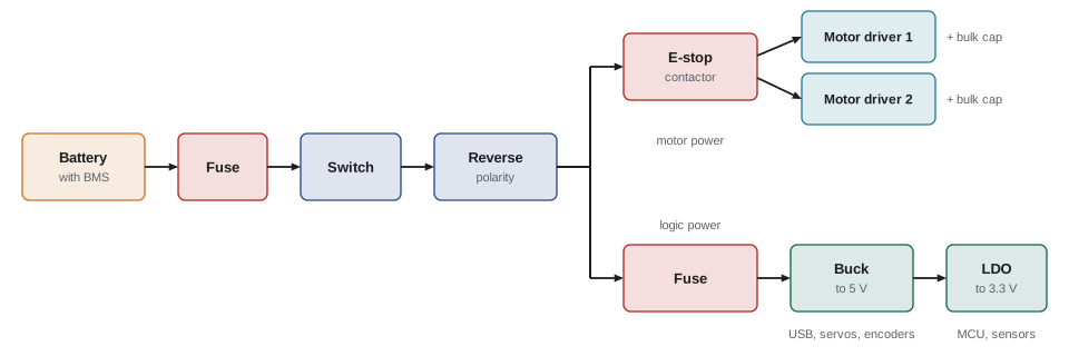
A good robot power system has, in order from the battery: a fuse or circuit breaker sized to protect the main wiring; a main switch or contactor; an emergency stop circuit that removes motor power without necessarily cutting the computer; reverse-polarity protection, often a MOSFET arranged as an ideal diode; and separate fused branches for the motor drivers and the logic supplies. Bulk capacitors near each motor driver supply the brief current spikes motors demand, so those spikes do not travel back through the wiring and disturb everything else.
Fuses are chosen by current rating, voltage rating, and interrupting capacity, the largest fault current they can safely break. A lithium pack can deliver hundreds or thousands of amperes into a short circuit, so automotive blade fuses rated for 32 V DC are fine for small 12 V robots, but 48 V systems need fuses rated for at least that voltage. Inrush current, the surge that charges the bulk capacitors when the robot is switched on, can be tens or hundreds of amperes for a millisecond; it pits switch contacts and causes sparks at connectors. Precharge resistors or soft-start circuits limit it on larger robots.
Charging, storage and transport
Lithium-ion cells charge in two phases: constant current, usually 0.5C, until the cell reaches 4.2 V, then constant voltage while the current tapers. Use a charger designed for the exact chemistry and series count, never charge below 0 °C, and do not leave packs charging unattended on flammable surfaces. For storage longer than a few weeks, keep packs at roughly 40 to 60 % charge in a cool place; stored full, they age faster.
Shipping lithium batteries is regulated as hazardous materials. In the United States, PHMSA's Hazardous Materials Regulations (49 CFR, especially § 173.185) apply, and the FAA enforces them for air transport alongside the ICAO Technical Instructions. Lithium-ion batteries are UN 3480 when shipped alone and UN 3481 when packed with or contained in equipment. By air, batteries shipped alone must be at no more than 30 % state of charge, batteries over 100 Wh face stricter rules, and passengers may carry spare batteries up to 100 Wh in carry-on baggage only, or 101 to 160 Wh with airline approval. Cells must have passed the UN 38.3 tests. Used batteries should go to a battery recycler such as a Call2Recycle drop-off; several states, including Vermont, Colorado, Washington and Illinois, have battery stewardship laws.
These rules matter to robotics teams traveling to competitions and to companies shipping robots to customers. A robot with a 300 Wh pack cannot go in checked luggage, and shipping it as cargo requires trained staff, proper packaging and labels. Many teams buy or ship packs separately and plan around the 100 Wh threshold when choosing pack sizes.
Common mistakes
MistakeComparing battery packs by mAh alone.
InsteadCompare watt-hours, which account for voltage, and check the discharge rating.
MistakeDesigning regulators for the nominal battery voltage only.
InsteadDesign for the full range, from full charge down to empty with voltage sag at peak current.
MistakeUsing a linear regulator for a large voltage drop at high current.
InsteadUse a switching regulator, or calculate the heat and provide for it.
MistakeRunning lithium packs without a BMS or charging them with the wrong charger.
InsteadUse a BMS that protects every cell group and a charger matched to the chemistry and series count.
MistakePutting the emergency stop in software or cutting all power including the computer.
InsteadUse a hardware stop that removes motor power directly; keeping logic powered helps diagnosis.
Summary and key terms
- Packs combine cells in series (voltage) and parallel (capacity); lithium chemistries dominate, with LFP chosen for safety and cycle life.
- Runtime ≈ usable energy divided by average power; derate for depth of discharge, efficiency, cold and aging.
- C-rate expresses current relative to capacity; internal resistance causes voltage sag and heating at high current.
- A BMS monitors and balances cells and disconnects the pack before limits are exceeded.
- Linear regulators waste (Vin − Vout) × I; switching regulators reach 85 to 95 % efficiency but add noise.
- Fuse at the battery, separate motor and logic branches, add bulk capacitance and a hardware emergency stop.
- Lithium batteries are dangerous goods in transport; 100 Wh and 30 % state of charge are key thresholds for air.
- Cell
- A single electrochemical unit with a voltage set by its chemistry.
- 4S2P
- A pack configuration of four cells in series and two strings in parallel.
- Ampere-hour
- A unit of charge: one ampere for one hour, 3,600 coulombs.
- C-rate
- Current expressed as a multiple of a battery's capacity in ampere-hours.
- Internal resistance
- The resistance inside a cell that causes voltage sag and heating under load.
- Thermal runaway
- A self-heating failure in which a cell's temperature rises uncontrollably, often leading to venting or fire.
- Battery management system
- Electronics that monitor, protect and balance the cells of a pack.
- LDO regulator
- A linear regulator that works with a small difference between input and output voltage.
- Buck converter
- A switching regulator that steps a DC voltage down efficiently.
- Inrush current
- The brief surge when power is first applied and capacitors charge.
Practice problems
Work each problem on paper first, then reveal the answer to check.
What is the nominal voltage of a 6S lithium-ion pack?
Show answer
About 6 × 3.6 = 21.6 V (25.2 V full).
A 3S2P pack uses 2.5 Ah cells. What are its capacity and nominal energy?
Show answer
5 Ah and about 3 × 3.6 × 5 = 54 Wh.
What current is 2C for a 6 Ah pack?
Show answer
12 A.
A 4S1P pack of 30 mΩ cells delivers 10 A. How much does its voltage sag?
Show answer
4 × 0.030 × 10 = 1.2 V.
A linear regulator drops 12 V to 5 V at 0.5 A. What power does it dissipate?
Show answer
3.5 W.
A buck converter delivers 10 W at 90 % efficiency. How much power does it waste?
Show answer
About 1.1 W.
A robot has 180 Wh of usable energy and averages 60 W. Estimate its runtime.
Show answer
About 3 hours.
Why should lithium packs be stored partly charged?
Show answer
High states of charge accelerate aging; 40 to 60 % slows it.
Name two things a BMS does besides cutting off on overvoltage.
Show answer
Balances cells; protects against undervoltage, overcurrent and over-temperature; estimates state of charge.
Can a 160 Wh spare battery travel in checked airline baggage?
Show answer
No; spare lithium batteries go in carry-on only, and 101 to 160 Wh needs airline approval.
Lesson quiz · 5 questions
Score 60% or more to complete this lesson.
Create a free account to save your progress, take quizzes and earn a certificate.