
ROB-200 · Lesson 10 of 12 · 25 min
CAN and robot networks
As robots grow, their electronics spread out. A legged robot may have a dozen motor controllers in its joints, a battery management system in its body, force sensors in its feet and a computer in its head, all of which must exchange data reliably, many times a second, over cables running past powerful motors. On-board buses such as I2C and SPI cannot do this. Controller Area Network (CAN), invented by Bosch in the 1980s for cars, can: it is robust against noise, needs only two wires shared by every node, resolves collisions without losing data and is supported by most microcontrollers and every Linux computer through inexpensive adapters. This lesson explains how CAN works at the electrical and frame level, how to calculate bit timing and bus load, what CAN FD adds, the higher-level protocols robots use on top of CAN, and how microcontrollers join the ROS 2 world through micro-ROS.
Differential signaling and the physical layer
CAN uses two wires, CAN_H and CAN_L, twisted together. A transceiver chip converts the controller's logic signals into a difference between them. In the recessive state, logic 1, both wires sit at about 2.5 V with no difference. In the dominant state, logic 0, the transceiver drives CAN_H up to about 3.5 V and CAN_L down to about 1.5 V, a 2 V difference. Receivers look only at the difference, so noise coupled equally into both twisted wires, common-mode noise, cancels out. This is why CAN works beside motor cables where single-ended signals fail.
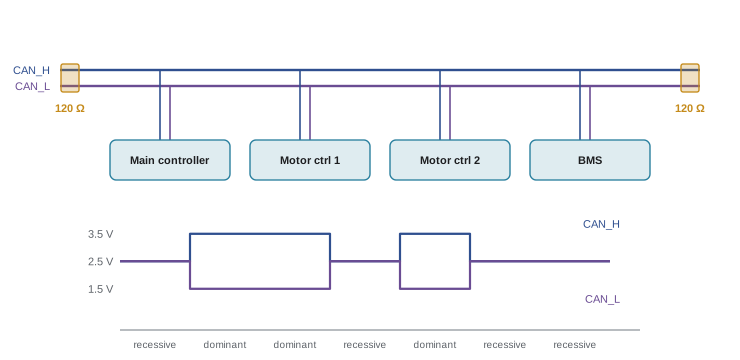
The bus is a single line with a 120 Ω termination resistor at each physical end, matching the cable's characteristic impedance so signals do not reflect from the ends. Together the two resistors make 60 Ω, which you can check with a multimeter across CAN_H and CAN_L with the power off: 60 Ω means both terminators are present, 120 Ω means one is missing, and a much lower value means too many. Nodes connect with short stubs; long branches cause reflections. A missing or doubled terminator is one of the most common causes of CAN problems on student robots.
Frames, identifiers and arbitration
CAN does not address nodes; it labels messages. Each frame carries an identifier, 11 bits in the standard format or 29 bits in the extended format, that says what the data are, such as "joint 3 position" or "battery status", and every node receives every frame and decides by identifier whether it cares, usually with hardware acceptance filters. A classic CAN frame carries 0 to 8 data bytes, plus a 15-bit CRC, an acknowledgment slot that every receiver fills to confirm correct reception, and control fields.
The identifier also sets priority. Any node may start transmitting when the bus is idle, so two nodes may start together. Each transmitter monitors the bus while sending. Because a dominant 0 overrides a recessive 1, a node that sends a 1 but sees a 0 knows that another node with a lower identifier is sending, stops immediately and tries again later. The frame with the lowest identifier wins without being damaged or delayed. This non-destructive bitwise arbitration means urgent messages, such as emergency stops, always get through first if they are given low identifiers.
def arbitrate(ids, bits=11):
    """Simulate CAN arbitration: dominant 0 beats recessive 1."""
    contenders = list(ids)
    for b in range(bits - 1, -1, -1):
        bus = min((i >> b) & 1 for i in contenders)   # wired-AND: any 0 wins
        lost = [i for i in contenders if (i >> b) & 1 != bus]
        for i in lost:
            print(f"  bit {b:2d}: 0x{i:03X} sent 1, saw 0 -> backs off")
        contenders = [i for i in contenders if (i >> b) & 1 == bus]
    return contenders[0]

ids = [0x123, 0x0A0, 0x0A4, 0x300]
print("contending:", [hex(i) for i in ids])
print(f"winner: 0x{arbitrate(ids):03X}")contending: ['0x123', '0xa0', '0xa4', '0x300'] bit 9: 0x300 sent 1, saw 0 -> backs off bit 8: 0x123 sent 1, saw 0 -> backs off bit 2: 0x0A4 sent 1, saw 0 -> backs off winner: 0x0A0
CAN also handles errors in hardware. Every node checks every frame's CRC, bit stuffing and format, and any node that detects an error destroys the frame with an error flag, so the sender retransmits it automatically. Nodes count their errors; one that keeps causing them becomes error passive and finally bus-off, disconnecting itself so that a faulty node cannot jam the network. For a robot, bus-off on a motor controller should trigger a safe stop and a clear fault report.
Bit timing and bit rate
Classic CAN runs at up to 1 Mbit/s, with 500 kbit/s and 250 kbit/s common. The bit rate is limited by the bus length, because every node must see each bit, including the dominant bits of others during arbitration, within one bit time. As a rule of thumb, 1 Mbit/s allows about 40 m and 125 kbit/s about 500 m. Each bit is divided into time quanta derived from the controller's clock: a synchronization segment, propagation and phase segments, and a sample point, usually set at 75 to 87.5 % of the bit. All nodes must use the same bit rate and similar sample points, and clock tolerance is tight, typically under 0.5 %, so CAN nodes need crystals.
Worked problem
Configuring CAN bit timing
A microcontroller's CAN peripheral runs from a 40 MHz clock. Configure 500 kbit/s with a sample point near 80 %.
Show solution
- Choose 20 time quanta per bit: \( 500\,000 \times 20 = 10 \) MHz quantum rate, so the prescaler divides by 4.
- Sync segment is always 1 quantum. For an 80 % sample point, sample after 16 quanta: \( 1 + \text{TSEG1} = 16 \), so TSEG1 = 15 and TSEG2 = 4.
- Check: \( 40\,\text{MHz} / (4 \times (1 + 15 + 4)) = 500 \) kbit/s, sample point \( 16/20 = 80\% \).
Answer: Prescaler 4, TSEG1 = 15, TSEG2 = 4, with a synchronization jump width of a few quanta. Online calculators and vendor tools produce these values.
Bus load
A CAN bus should not run close to full capacity, because lower-priority messages are delayed when higher-priority traffic keeps winning arbitration. Designers aim to keep average load under about 50 to 70 %. To estimate load, count the bits per frame, including stuff bits: the transmitter inserts an opposite bit after five identical bits so receivers stay synchronized, which can add up to about 20 % in the worst case. A standard-format classic frame with 8 data bytes is about 111 bits before stuffing and up to about 135 with worst-case stuffing, plus 3 bits of interframe space.
def frame_bits(data_bytes, extended=False, worst_stuffing=True):
    base = (64 if extended else 44) + 8 * data_bytes   # SOF to EOF
    stuffable = (54 if extended else 34) + 8 * data_bytes
    stuff = (stuffable - 1) // 4 if worst_stuffing else 0
    return base + stuff + 3                             # + interframe space

def bus_load(messages, bitrate):
    bits = sum(rate * frame_bits(n) for n, rate in messages)
    return bits / bitrate

# 12 joint controllers each send state (8 bytes) at 200 Hz and receive
# a command (8 bytes) at 200 Hz; the BMS sends 4 bytes at 10 Hz.
msgs = [(8, 200)] * 24 + [(4, 10)]
for br in (500_000, 1_000_000):
    print(f"{br//1000:5d} kbit/s: load = {bus_load(msgs, br)*100:5.1f} %")
print("bits per 8-byte frame (worst case):", frame_bits(8))500 kbit/s: load = 129.8 % 1000 kbit/s: load = 64.9 % bits per 8-byte frame (worst case): 135
The twelve-joint robot overloads a 500 kbit/s bus and uses most of a 1 Mbit/s bus, too much for comfort. Designers would split the joints across two or more CAN buses, as many legged robots do with one bus per leg, reduce rates, pack data more efficiently, or move to CAN FD.
CAN FD and beyond
CAN FD (flexible data rate), standardized in ISO 11898-1 since 2015, keeps classic CAN's arbitration at the normal bit rate but switches to a faster rate, commonly 2 to 5 Mbit/s and up to 8 Mbit/s, for the data phase, and allows up to 64 data bytes per frame with a stronger CRC. A 64-byte CAN FD frame at a 5 Mbit/s data rate carries eight times the payload of a classic frame in roughly the same time, which is why modern robot joint controllers and vehicles increasingly use it. CAN FD controllers can talk to classic CAN nodes only if no FD frames are sent, so a bus is usually all FD or all classic. A newer generation, CAN XL, added to the standard in 2024, extends frames to 2,048 bytes and data rates beyond 10 Mbit/s, but at the time of writing it is only beginning to appear in vehicles.
| Classic CAN | CAN FD | Industrial Ethernet (e.g. EtherCAT) | |
|---|---|---|---|
| Payload per frame | 0 to 8 bytes | 0 to 64 bytes | Up to about 1,500 bytes |
| Bit rate | Up to 1 Mbit/s | 1 Mbit/s arbitration, 2 to 8 Mbit/s data | 100 Mbit/s and above |
| Wiring | One twisted pair, multi-drop | One twisted pair, multi-drop | Point-to-point or daisy-chained Ethernet cables |
| Typical robot use | Small robots, battery packs, simple joints | Joint controllers, mobile bases | Industrial arms, humanoids, high-rate synchronized joints |
Higher-level protocols
CAN defines frames, not meanings. Higher-level protocols assign identifiers and define message contents so devices from different vendors interoperate. CANopen, from industrial automation, defines device profiles for motor drives (CiA 402), process data objects for fast cyclic data, service data objects for configuration and a network management state machine; many commercial servo drives speak it. DroneCAN and its successor Cyphal define publish-subscribe messages for drones and robots and are used in popular flight-controller ecosystems. SAE J1939 is used in heavy vehicles and agricultural machinery, which matters for field robots built on tractor platforms. Many robot motor controllers simply define their own simple protocol, which is fine within one robot but makes mixing vendors harder.
On Linux, CAN adapters appear as network interfaces through SocketCAN, part of the kernel. You bring an interface up with the ip command and use the can-utils tools to send, dump and log frames, and programs open CAN sockets much as they open network sockets. ROS 2 drivers for CAN-based motor controllers are built on SocketCAN.
# Bring up a CAN interface at 1 Mbit/s and watch traffic (Linux, can-utils)
sudo ip link set can0 type can bitrate 1000000
sudo ip link set can0 up
candump can0                       # print every frame
cansend can0 123#11223344          # send ID 0x123 with 4 data bytes
ip -details -statistics link show can0   # error counters, bus-off state
micro-ROS: microcontrollers in the ROS 2 graph
In ROB-110 you wrote ROS 2 nodes on Linux. micro-ROS brings ROS 2 concepts, nodes, publishers, subscribers, services and parameters, to microcontrollers. It runs on top of a real-time operating system such as FreeRTOS or Zephyr, or bare metal on some platforms, and communicates through the DDS-XRCE protocol, a lightweight relative of the DDS middleware ROS 2 uses. A micro-ROS agent running on the Linux computer bridges the microcontroller's traffic, over a serial link, USB or UDP, into the normal ROS 2 graph, so a motor controller's encoder counts can appear as an ordinary ROS 2 topic.
micro-ROS suits microcontrollers with at least tens of kilobytes of RAM, such as ESP32, STM32 and RP2040-class chips. It is not the only option: many teams keep a simple custom serial or CAN protocol between the microcontroller and a ROS 2 driver node on Linux, which can be easier to debug and lighter on resources. Either way, the principle of lesson 5 holds: the microcontroller does the hard real-time work and enforces safety, and the Linux side plans and coordinates.
Common mistakes
MistakeLeaving out a termination resistor or fitting one on every node.
InsteadFit exactly two 120 Ω terminators at the physical ends; check for 60 Ω with power off.
MistakeRunning CAN nodes on internal RC oscillators.
InsteadUse crystals; CAN timing tolerance is tight.
MistakeGiving emergency or control messages high identifiers.
InsteadAssign low identifiers to the most urgent messages so they win arbitration.
MistakePlanning bus traffic near 100 % load.
InsteadKeep average load under about 50 to 70 %; split buses or move to CAN FD.
MistakeIgnoring error counters and bus-off events.
InsteadMonitor them and make bus-off on a motor controller trigger a safe stop.
Summary and key terms
- CAN uses a terminated differential twisted pair that rejects common-mode noise.
- Frames carry identifiers, not addresses; every node receives every frame and filters by ID.
- Bitwise arbitration lets the lowest identifier win without corrupting frames.
- Hardware CRC checks, acknowledgments, retransmission and bus-off isolation make CAN robust.
- Bit timing divides each bit into quanta; bus length limits bit rate; keep load under about 50 to 70 %.
- CAN FD adds a fast data phase and 64-byte payloads; CANopen, DroneCAN/Cyphal and J1939 add meaning.
- SocketCAN connects CAN to Linux; micro-ROS brings ROS 2 nodes to microcontrollers via an agent.
- Differential signaling
- Sending a signal as the difference between two wires so common noise cancels.
- Termination resistor
- A resistor matching the cable impedance at each bus end to prevent reflections.
- CAN identifier
- The 11- or 29-bit field that labels a message and sets its priority.
- Arbitration
- The process by which the lowest-identifier frame wins access to the bus.
- Dominant and recessive
- The CAN bus states representing 0, which overrides, and 1.
- Bit stuffing
- Inserting an opposite bit after five identical bits to keep receivers synchronized.
- Bus-off
- The state in which a CAN node with too many errors disconnects itself.
- CAN FD
- CAN with a flexible data rate and payloads of up to 64 bytes.
- SocketCAN
- The Linux kernel's network-socket interface to CAN hardware.
- micro-ROS
- A framework that runs ROS 2 nodes on microcontrollers, bridged by an agent.
Practice problems
Work each problem on paper first, then reveal the answer to check.
What resistance should you measure between CAN_H and CAN_L on a correctly terminated, unpowered bus?
Show answer
60 Ω.
Two nodes send IDs 0x210 and 0x20F at once. Which wins?
Show answer
0x20F, the lower identifier.
Why does twisting CAN_H and CAN_L help?
Show answer
Noise couples equally into both wires and cancels in the difference.
What does a node do when it sends a recessive bit but reads a dominant one during arbitration?
Show answer
It stops transmitting and retries later.
A 40 MHz clock uses prescaler 5 and 16 quanta per bit. What is the bit rate?
Show answer
500 kbit/s.
Roughly how long can a 1 Mbit/s CAN bus be?
Show answer
About 40 m.
A bus carries 2,000 frames per second of 130 bits at 500 kbit/s. What is the load?
Show answer
52 %.
How many data bytes can a CAN FD frame carry?
Show answer
Up to 64.
Name a CAN higher-level protocol for motor drives.
Show answer
CANopen with the CiA 402 drive profile.
What component bridges a micro-ROS microcontroller into the ROS 2 graph?
Show answer
The micro-ROS agent running on the Linux computer.
Lesson quiz · 5 questions
Score 60% or more to complete this lesson.
Create a free account to save your progress, take quizzes and earn a certificate.