
RCDD-110 · Lesson 4 of 12 · 20 min
Copper performance parameters: attenuation, crosstalk and return loss
▶ Video coming soon A video version of this lesson is on the way.
Tomasz Wiercinski, the cabling foreman on Harbourview, emails Daniel a certification report from a mock-up the contractor built in the site trailer: one Category 6A permanent link with a jack at the outlet and a patch panel at the telecommunications room. The report runs to three pages of graphs and tables. Tomasz has a question: the link passed, but one line shows a margin of only 1.2 dB on 'PS NEXT' at the remote end. Should they worry? Daniel used to read these reports for the overall pass or fail. Now he needs to understand every line, because the design specification he is writing will decide which results are acceptable.
Every balanced cabling standard defines a set of transmission parameters, each measured across the specified frequency range and compared with a limit line. Some describe how much signal survives, some describe how much unwanted energy arrives, and some combine the two. This lesson walks through the main parameters in the order they usually appear on a certification report, and shows how each one relates to the signal-to-noise idea from Lessons 1 and 2.
Insertion loss
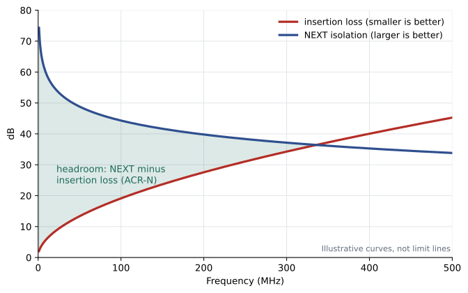
Insertion loss, still often called attenuation, is the reduction in signal power from one end of a link or channel to the other, expressed in decibels. It rises with frequency and with length. At low frequencies most of the loss comes from the resistance of the copper. At higher frequencies two effects dominate: the skin effect, which forces current toward the outer surface of each conductor so that less copper carries it, and dielectric loss in the insulation. Both increase with frequency, which is why the insertion loss curve of a cable rises steeply across its frequency range.
Insertion loss also rises with temperature. Copper resistance increases as it warms, and some insulation materials lose more at higher temperature. Cabling standards specify loss at 20 degrees Celsius and give derating factors for higher temperatures. In practice this means that a channel in a hot ceiling space or a large bundle carrying Power over Ethernet current may need to be shorter than 100 m to stay within the insertion loss limit. Some standards and manufacturers express this as a reduced maximum length for warm environments.
Worked problem
Loss and length
A cable has an insertion loss of 31 dB per 100 m at 400 MHz at 20 degrees Celsius. Ignoring connectors and temperature, what is the loss of 75 m of this cable at that frequency?
Show solution
- Loss in dB is proportional to length: 31 × 75/100 = 23.25 dB.
Answer: About 23.3 dB. Doubling the length doubles the loss in decibels.
Near-end crosstalk (NEXT)
Crosstalk is signal energy that couples from one pair onto another. Near-end crosstalk is measured at the same end of the cable as the transmitter: a signal is injected into one pair and the tester measures how much appears on another pair at that end. NEXT is expressed as isolation, the number of decibels by which the coupled signal is weaker than the injected one. Larger values are better.
NEXT is usually the most demanding crosstalk parameter because the disturbing signal is at full strength when it couples, while the wanted signal arriving from the far end on the other pair has been weakened by the whole length of the cable. Most NEXT occurs within the first few meters from the transmitter, and especially at the connectors, where pairs are untwisted and close together. That is why connector quality and termination workmanship dominate NEXT results, and why many NEXT failures are fixed by re-terminating rather than replacing the cable.
Because NEXT is measured at each end, a full certification tests it from both ends of the link. A report showing NEXT at the 'main' and 'remote' ends is not measuring two different things; it is checking the connections at each end.
Power sum NEXT
In a four-pair cable carrying a four-pair application, each pair suffers crosstalk from all three of the others at once. Power sum NEXT (PS NEXT) combines the NEXT from the three disturbing pairs into one value for each disturbed pair, by adding the coupled powers. Because powers add, PS NEXT is always a little worse than the worst individual pair-to-pair NEXT value.
Worked problem
Power summing three disturbers
On one pair, the NEXT from the three other pairs is 45 dB, 48 dB and 50 dB. What is the PS NEXT?
Show solution
- Convert each to a power ratio: \(10^{-4.5} = 3.16 \times 10^{-5}\), \(10^{-4.8} = 1.58 \times 10^{-5}\), \(10^{-5.0} = 1.00 \times 10^{-5}\).
- Add: \(5.74 \times 10^{-5}\).
- Convert back: \(-10 \log_{10}(5.74 \times 10^{-5}) \approx 42.4\) dB.
Answer: About 42.4 dB, worse than any single disturber. This is the same rule as adding noise powers in Lesson 2.
Far-end crosstalk and ACR-F
Far-end crosstalk (FEXT) is measured at the opposite end from the transmitter: the coupled signal on another pair has traveled the whole length of the cable, just as the wanted signal has. Raw FEXT therefore depends on length, so standards express it as the attenuation-to-crosstalk ratio, far end (ACR-F). ACR-F is the FEXT isolation minus the insertion loss of the disturbed pair. It tells you how far the wanted signal at the receiver sits above the far-end crosstalk. Older documents called this equal level far-end crosstalk (ELFEXT). Power sum ACR-F (PS ACR-F) combines the three disturbing pairs.
ACR-F and PS ACR-F matter most for applications that send in the same direction on several pairs at once, which all modern four-pair Ethernet does. Like NEXT, larger values are better.
ACR-N: a figure of merit
Attenuation-to-crosstalk ratio, near end (ACR-N), is NEXT minus insertion loss at each frequency. It describes how far the wanted signal from the far end sits above the near-end crosstalk at the receiver. It is the closest single parameter to a signal-to-noise ratio for a channel, and some reports show it as the gap between the insertion loss and NEXT curves in the figure above. Standards treat ACR-N as informative or calculated rather than as a separate pass or fail test in many cases, but it is a useful way to see how much headroom a channel has and where in the frequency range that headroom runs out.
Return loss
Return loss measures reflected energy. A signal is sent into a pair and the tester measures how much comes back to the same end, caused by impedance variations along the link, at connectors, in patch cords and at any point where the cable has been damaged or deformed. It is expressed in decibels below the incident signal, so larger values are better. Return loss matters because full-duplex applications transmit and receive on the same pair; the echo cancellation circuits must remove reflections, and large or irregular reflections can overwhelm it.
Return loss is tested from both ends. Return loss failures are often caused by mismatched components, such as a patch cord or jack from a different category or manufacturer than the rest of the channel, by kinked or crushed cable, or by untwisted pairs at a termination.
Propagation delay, skew and DC parameters
Propagation delay is the time for a signal to travel the length of the pair, and delay skew is the difference between the fastest and slowest pairs, as introduced in Lesson 1. Standards set maximum values for a full channel. Skew depends on the different twist rates of each pair, since a more tightly twisted pair is physically longer than the cable that contains it.
Direct current parameters matter for powered applications. DC loop resistance is the total resistance of the two conductors of a pair connected at the far end. Resistance unbalance within a pair and between pairs, described in Lesson 3, affects how evenly Power over Ethernet current divides. Testers also check wire map, which confirms that each conductor is connected to the correct pin at each end and detects opens, shorts, reversed pairs, crossed pairs and split pairs. A split pair passes a simple continuity test but destroys balance, because the two conductors of a 'pair' are actually from different twisted pairs.
Alien crosstalk
Alien crosstalk is crosstalk from pairs in neighboring cables rather than from pairs within the same cable. It matters for applications that use the full frequency range of Category 6A, such as 10GBASE-T, because, as explained in Lesson 1, the transceivers cannot cancel noise from cables they cannot see. Standards define power sum alien NEXT (PS ANEXT) and power sum alien ACR-F (PS AACR-F), measured between a disturbed link and the links bundled around it. Alien crosstalk testing is time-consuming, so it is usually done on a sample of links in the most demanding positions, such as the center of a large bundle, rather than on every link.
| Parameter | What it measures | Better when |
|---|---|---|
| Insertion loss | Signal power lost end to end | Smaller |
| NEXT and PS NEXT | Crosstalk at the transmitting end | Larger |
| ACR-F and PS ACR-F | Far-end crosstalk relative to the received signal | Larger |
| ACR-N | Near-end crosstalk relative to the received signal | Larger |
| Return loss | Energy reflected back to the source | Larger |
| Propagation delay and skew | Signal travel time and pair-to-pair difference | Smaller |
| PS ANEXT and PS AACR-F | Crosstalk from neighboring cables | Larger |
| TCL and ELTCTL | Balance (mode conversion) | Larger |
Channels, permanent links and limits
Every parameter has limits for a channel and for a permanent link. The channel is the full end-to-end path, including equipment cords and patch cords, up to 100 m in the standard model. The permanent link is the fixed portion, from the patch panel to the outlet, including an optional consolidation point, up to 90 m. Owners and designers usually require certification of the permanent link, because the cords will be changed many times over the life of the building. Limits are stricter for the permanent link because it contains fewer connections and less length than a channel.
Certification testers apply the limits of a specific standard, and the result must name that standard. A link certified to an ISO/IEC class limit has not automatically been certified to a TIA category limit, even where the two are very similar. The design specification should state which standard and which test limit apply.
Reading the marginal result
Daniel returns to Tomasz's question. The link passed PS NEXT at the remote end with 1.2 dB of margin. Every other parameter shows 4 dB or more. A result that much worse at one end, on a near-end parameter, points to the termination at that end rather than the cable. Daniel asks Tomasz how the outlet was terminated. It turns out the installer was new and trimmed the jacket back further than the connector instructions allowed, leaving more pair untwist. Re-terminating raises the margin to 4.6 dB. The link passed either way, but the design specification will now require terminations to follow the manufacturer's untwist limit, and Roz adds a note that the contractor's first ten links on each floor will be reviewed in detail, not just for pass or fail.
Exam focus: what each failure points to
Certification reports are as useful for finding faults as for proving compliance. A few patterns recur. An insertion loss failure on all pairs usually means the link is too long or too hot, or that the wrong grade of cable was installed. A NEXT failure at one end usually points to the termination at that end. Return loss failures often come from mismatched components or damaged cable, and testers that show the distance to the fault help find them. A wire map failure is a wiring error that must be corrected before anything else is meaningful.
Common mistakes
MistakeThinking NEXT failures mean the cable is bad.
InsteadMost NEXT is generated at connectors and in the first meters of cable. Re-terminating usually fixes it.
MistakeTreating PS NEXT as an average of the pair values.
InsteadPower sums add the coupled powers, so PS NEXT is always slightly worse than the worst single pair.
MistakeAssuming insertion loss limits hold at any temperature.
InsteadLoss rises with temperature, so hot spaces and large PoE bundles may need shorter links.
MistakeCertifying permanent links against channel limits.
InsteadPermanent links have stricter limits. The tester must apply the correct link model and standard.
Summary and key terms
- Insertion loss rises with frequency, length and temperature; smaller is better.
- NEXT is measured at the transmitting end and is dominated by connectors; PS NEXT power-sums three disturbers.
- ACR-F expresses far-end crosstalk relative to the received signal; ACR-N plays the same role at the near end.
- Return loss measures reflections from impedance variations; larger values are better and both ends are tested.
- Alien crosstalk from neighboring cables cannot be canceled by transceivers and is controlled for Category 6A applications.
- Permanent link limits are stricter than channel limits, and test results must name the standard used.
- Insertion loss
- The reduction in signal power from one end of a link or channel to the other, in dB.
- NEXT
- Near-end crosstalk: signal coupled from one pair to another, measured at the transmitting end.
- ACR-F
- Attenuation-to-crosstalk ratio, far end: far-end crosstalk isolation minus insertion loss.
- Return loss
- The ratio of incident to reflected power at a port, in dB, caused by impedance variations.
- Alien crosstalk
- Crosstalk coupled between pairs of different cables.
- Permanent link
- The fixed part of a horizontal cabling path, from patch panel to outlet, excluding cords.
Practice problems
Work each problem on paper first, then reveal the answer to check.
Two disturbing pairs each give 46 dB of NEXT on a third pair. What is the power sum?
Show answer
Equal powers add to double, so PS NEXT is 46 − 3 = 43 dB.
Why is ACR-F used instead of raw FEXT?
Show answer
Raw FEXT depends on length because both the crosstalk and the wanted signal are attenuated along the cable. Subtracting insertion loss gives a length-independent measure of how far the signal sits above the crosstalk.
Which parameter detects a split pair?
Show answer
Wire map, which checks pin-to-pin connections and detects pairs whose conductors come from different twisted pairs.
Lesson quiz · 5 questions
Score 60% or more to complete this lesson.
Create a free account to save your progress, take quizzes and earn a certificate.