
RCDD-110 · Lesson 2 of 12 · 22 min
Decibels and power ratios for designers
▶ Video coming soon A video version of this lesson is on the way.
Daniel's first real task on Harbourview is to check a vendor's proposal for the campus fiber link to the existing college building 400 m away. The proposal is full of numbers: insertion loss in decibels, transmitter power in dBm, receiver sensitivity in dBm, a 'link margin' of 6.2 dB. He knows that a lower insertion loss is better, but he cannot say whether 6.2 dB of margin is generous or dangerous. Roz takes the proposal, circles every number with a 'dB' in it, and says, 'Before you check a single one of these, you need to be able to do decibel arithmetic in your head. Every lesson after this one depends on it.'
The decibel is the working language of transmission design. Loss, gain, crosstalk, return loss, noise, optical power, radio signal strength and even sound in a classroom are all expressed in decibels. Designers like decibels because they turn multiplication into addition. A chain of cables, connectors and splices, each of which passes on only part of the signal, can be analyzed by adding up a column of numbers. This lesson builds the arithmetic you will use for the rest of the course.
Why a logarithmic unit?
Signals in communications systems vary over enormous ranges. A wireless access point might transmit a tenth of a watt, while the signal arriving at a phone across the room is less than a billionth of a milliwatt. Writing those numbers as plain powers is clumsy, and multiplying long chains of tiny fractions invites mistakes. A logarithmic scale compresses that range. Every factor of ten in power becomes a step of 10 dB, so a range of a trillion to one becomes a manageable 120 dB.
There is also a physical reason. Loss in a uniform cable is exponential: each meter passes on the same fraction of the power that enters it. If one meter passes on 0.95 of the power, two meters pass on 0.95 squared, and a hundred meters pass on 0.95 to the hundredth power. In decibels, that exponential becomes a straight line: loss in dB is simply proportional to length. This is why cable attenuation is quoted in dB per 100 m or dB per kilometer.
The definition
A decibel value expresses the ratio of two powers. If power \(P_2\) is compared with a reference power \(P_1\), the ratio in decibels is ten times the base-ten logarithm of the power ratio. A positive value means \(P_2\) is larger (a gain); a negative value means it is smaller (a loss). When we talk about loss we usually drop the minus sign and say 'a loss of 3 dB'.
Voltages and currents need a different multiplier. Power in a resistive load is proportional to the square of the voltage, so a voltage ratio must be squared before it becomes a power ratio. Because the logarithm of a square is twice the logarithm, voltage ratios use twenty times the logarithm. This only gives the same answer as the power formula when both voltages are measured across the same impedance, which is true in a properly matched 100 ohm twisted-pair channel.
Numbers worth memorizing
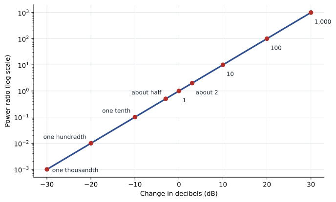
A few values come up so often that experienced designers know them without a calculator. They let you estimate quickly and catch errors in other people's numbers.
| Change in dB | Power ratio | Voltage ratio |
|---|---|---|
| +3 dB | about 2 times | about 1.41 times |
| +6 dB | about 4 times | about 2 times |
| +10 dB | 10 times | about 3.16 times |
| +20 dB | 100 times | 10 times |
| −3 dB | about half | about 0.71 |
| −10 dB | one tenth | about 0.32 |
| −20 dB | one hundredth | one tenth |
| −30 dB | one thousandth | about 0.032 |
With these values you can break almost any decibel figure into pieces. A loss of 13 dB is 10 dB plus 3 dB, so the power is one tenth of one half, or one twentieth. A loss of 23 dB is one hundredth of one half, or one two-hundredth. A gain of 16 dB is ten times four, or forty times. Practice this until it is automatic.
Absolute levels: dBm and friends
A plain decibel value is always a ratio. To express an absolute power, designers fix the reference. The most common is the milliwatt: a power in dBm is the ratio of that power to one milliwatt, expressed in decibels. So 1 mW is 0 dBm, 10 mW is +10 dBm, 100 mW is +20 dBm, 1 W is +30 dBm, and 1 microwatt is −30 dBm.
Other references appear in specific fields. Radio engineers use dBi for antenna gain compared with an ideal isotropic antenna, and dBd for gain compared with a dipole. Broadband video systems often use dBmV, a voltage level referenced to one millivolt across 75 ohms. Audio systems use dBu and dBV, and sound pressure is measured in dB SPL. The exam expects you to recognize these suffixes and know that the letters tell you the reference.
A key rule: you can add or subtract plain decibel values from a dBm value, but you cannot add two dBm values. If a transmitter launches −3 dBm and the link has 4.5 dB of loss, the received power is −7.5 dBm. But two signals of 0 dBm each do not combine to 0 dBm plus 0 dBm; they combine to 2 mW, which is about +3 dBm. When you add powers, convert to milliwatts first.
Worked problem
A received optical power
A singlemode transceiver launches −2 dBm into a link with a measured loss of 3.6 dB. The receiver needs at least −14.4 dBm. What power reaches the receiver, and what margin remains?
Show solution
- Received power = launch power − loss = −2 − 3.6 = −5.6 dBm.
- Margin = received power − sensitivity = −5.6 − (−14.4) = 8.8 dB.
Answer: The receiver sees −5.6 dBm, giving 8.8 dB of margin above its sensitivity.
Adding up a chain
Because decibels turn multiplication into addition, the total loss of a chain of components is just the sum of their individual losses. A cable with 2.1 dB of loss, two connections with 0.3 dB each and a splice with 0.1 dB has a total loss of 2.8 dB. Gains, such as an amplifier or a directional antenna, are added with the opposite sign.
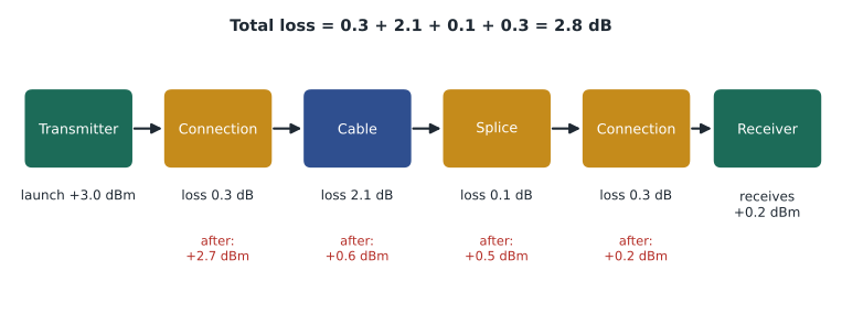
This is the core of every link budget, whether for copper, fiber or radio. Start with what the transmitter launches, subtract every loss, add every gain, and compare the result with what the receiver needs. The difference is the margin. A designer wants enough margin to absorb aging, repairs, dirty connectors, temperature changes and measurement uncertainty, but not so much that the receiver is overloaded on short links. Some short-reach optics specify a maximum received power as well as a minimum.
Worked problem
Converting a loss to a fraction
A permanent link shows 19 dB of insertion loss at its highest test frequency. What fraction of the signal power reaches the far end, and what fraction of the voltage?
Show solution
- Power: \(10^{-19/10} = 10^{-1.9} \approx 0.0126\), about one eightieth.
- Voltage: \(10^{-19/20} = 10^{-0.95} \approx 0.112\), about one ninth.
Answer: About 1.3 hundredths of the power and about 11 hundredths of the voltage survive. High-frequency loss is severe, and applications are designed to work with it.
Decibels in the test report
Almost every number on a copper certification report is in decibels. Insertion loss is how much signal is lost from one end to the other, so smaller is better. Near-end crosstalk, return loss and alien crosstalk are expressed as how far below the signal the unwanted energy sits, so larger is better. A NEXT value of 40 dB means the crosstalk is 40 dB weaker than the transmitted signal: one ten-thousandth of its power. Margin is the difference between a measured value and the limit. Positive margin means the link passes with room to spare; negative margin means it fails.
The sign conventions trip up many candidates. Some instruments and documents show loss as a negative gain, so a cable with 20 dB of loss may appear as −20 dB. Read the column heading. When in doubt, ask: is this a quantity where bigger is better (crosstalk isolation, return loss, margin) or one where smaller is better (insertion loss)?
Signal-to-noise ratio in decibels
Signal-to-noise ratio is usually quoted in decibels: \(\text{S/N}_{\text{dB}} = 10 \log_{10}(S/N)\). In a cabling channel, a useful approximation of how much clean signal is left at a given frequency is the difference between the crosstalk isolation and the insertion loss. If the far-end crosstalk isolation of a channel is 35 dB at some frequency, and insertion loss there is 20 dB, then the wanted signal at the receiver sits about 15 dB above the far-end crosstalk from that pair. Cabling standards express this idea through the attenuation-to-crosstalk ratio parameters you will meet in Lesson 4.
To use a decibel S/N in the Shannon formula from Lesson 1, convert it back to a ratio: 30 dB is 1,000, 20 dB is 100 and 15 dB is about 31.6. Remember that the formula needs the ratio, not the decibel value.
Worked problem
Combining two noise sources
At a receiver, crosstalk noise is −42 dBm and alien crosstalk noise is −45 dBm. What is the total noise power?
Show solution
- Convert to milliwatts: \(10^{-4.2} \approx 6.31 \times 10^{-5}\) mW and \(10^{-4.5} \approx 3.16 \times 10^{-5}\) mW.
- Add: \(9.47 \times 10^{-5}\) mW.
- Convert back: \(10 \log_{10}(9.47 \times 10^{-5}) \approx -40.2\) dBm.
Answer: About −40.2 dBm. Noise powers add as milliwatts, not as decibels. Two equal noise sources raise the total by 3 dB.
Back to the proposal
With a pencil and the table of common values, Daniel works through the vendor's proposal. The transceiver launch power and receiver sensitivity give a power budget of 12.4 dB. The vendor's calculated link loss is 6.2 dB, so they have called the remaining 6.2 dB 'margin'. Daniel checks the loss calculation and finds that the vendor used typical connector loss rather than the maximum allowed by the standard, and left out the patch panel at the far building. Using the standard's allowances, the loss comes to 7.4 dB and the margin to 5.0 dB. That is still healthy, but it is not what the proposal claimed, and Roz wants the design basis to use the conservative figure. 'Typical values are for marketing,' she says. 'Maximum values are for design.'
Exam focus: decibel shortcuts
Exam questions on decibels usually test whether you can move between ratios and decibels quickly and whether you apply the right rule to powers, voltages and levels. Three habits help. First, break any decibel value into tens and threes: 26 dB is 20 + 3 + 3, so a power ratio of about 100 × 2 × 2 = 400. Second, check the units in every answer choice. A question that asks for received power wants dBm; a question that asks for loss or margin wants dB. Third, when a question adds two signals or two noise sources, stop and convert to milliwatts before adding.
Watch also for questions that switch between voltage and power. If a voltage is halved, the power falls to one quarter, which is a 6 dB loss, not 3 dB. If a question gives a voltage gain of 10, that is 20 dB, not 10 dB. These are the most common traps in this topic.
Common mistakes
MistakeAdding dBm values directly.
InsteadConvert each power to milliwatts, add, and convert back. Only ratios in dB can be added to or subtracted from a level.
MistakeUsing 10 log for voltage ratios.
InsteadVoltage and current ratios use 20 log, because power depends on the square of voltage.
MistakeConfusing the sign of loss and isolation.
InsteadInsertion loss is better when smaller. Crosstalk isolation, return loss and margin are better when larger.
MistakeTreating dBi as the same as dB.
InsteaddBi is antenna gain referenced to an isotropic radiator. It is a gain added to a radio link budget, not a power level.
Summary and key terms
- A decibel value is ten times the logarithm of a power ratio, or twenty times the logarithm of a voltage ratio.
- 3 dB is about a factor of two in power; 10 dB is a factor of ten; 20 dB is a factor of one hundred.
- dBm is an absolute power referenced to one milliwatt; other suffixes such as dBi and dBmV name other references.
- Losses and gains in dB add along a chain; absolute powers must be converted to milliwatts before they are added.
- Margin is the difference between a measured or calculated value and the limit, and design should use maximum allowed values.
- Decibel (dB)
- A logarithmic unit for the ratio of two powers, equal to ten times the base-ten logarithm of the ratio.
- dBm
- A power level in decibels relative to one milliwatt.
- dBi
- Antenna gain in decibels relative to an ideal isotropic antenna.
- Insertion loss
- The reduction in signal power caused by inserting a component or channel into a path, in dB.
- Margin
- The amount by which a measured or calculated value is better than its limit, in dB.
- Link budget
- A calculation that adds gains and subtracts losses from launch power to find received power and margin.
Practice problems
Work each problem on paper first, then reveal the answer to check.
Express a power ratio of 50 in decibels.
Show answer
\(10 \log_{10} 50 \approx 17\) dB (10 dB for the factor of 10, plus about 7 dB for the factor of 5).
What is 250 mW in dBm?
Show answer
\(10 \log_{10} 250 \approx 24\) dBm.
A link loses 9 dB. Roughly what fraction of the power arrives?
Show answer
9 dB is 10 dB minus 1 dB, so about one eighth (more precisely 0.126).
Lesson quiz · 5 questions
Score 60% or more to complete this lesson.
Create a free account to save your progress, take quizzes and earn a certificate.