
RAC-320 · Lesson 4 of 12 · 18 min
Ductless mini-splits and multi-zone systems
The Haddads were happy with their attic. Two years earlier Northfield had put a single-zone ductless heat pump in their converted attic room, a 12,000 Btu/h R-410A inverter unit with one wall head, and the room had gone from the coldest in the house to the most comfortable. Now they wanted the same for the rest of the house. Their 1950s story-and-a-half had hot-water radiators and no ducts at all, so central air would have meant tearing open walls. Sami Haddad asked for a quote for "the same thing, everywhere." Dana took Theo to measure up. "Ductless is where a lot of our new work is," she said. "It looks simple. The installs that go wrong are the ones where nobody thought about the rooms."
This lesson covers ductless and mini-split equipment: the indoor unit types, single-zone and multi-zone outdoor units, how heads are chosen for rooms, combination ratios, line sets and flare joints, condensate, and the installation details that make these systems work or fail. The inverter technology inside them is the subject of lesson 5.
What a ductless system is
A ductless mini-split has an outdoor unit, almost always an inverter-driven heat pump, connected by small refrigerant lines and a power and communication cable to one or more indoor units. Each indoor unit has its own coil, fan, filter, electronic expansion valve or a valve in the outdoor unit, and controls, and it heats or cools the room it is in. There are no ducts, so there are no duct losses, and each room has its own temperature control.
Indoor units come in several styles:
- High-wall heads: the most common and least expensive, mounted high on a wall, blowing air across the room.
- Ceiling cassettes: recessed into the ceiling, blowing in two or four directions, common in commercial spaces and open rooms.
- Floor consoles: low on the wall, good for heating because they deliver warm air near the floor, and useful under windows or in rooms with sloped ceilings.
- Ducted slim units: small air handlers concealed in a ceiling or closet, serving one to three rooms through short ducts.
- Universal or under-ceiling units: suspended from the ceiling where a cassette cannot be recessed.
Outdoor units are either single-zone, with one indoor unit, or multi-zone, with two to eight indoor units on one outdoor unit. Single-zone systems are usually the most efficient and can reach the highest ratings, because the outdoor unit's compressor and valves are matched to one coil. Multi-zone systems save outdoor space and electrical circuits but are usually a little less efficient and more complex to troubleshoot.
Choosing heads for rooms
Ductless sizing starts with each room's load, not with the house total. Each head must be able to heat its room on the design day and cool it on the hottest afternoon, but no more than that, because an oversized head in a small room short-cycles in mild weather, controls humidity poorly in summer and can make the room feel drafty. Bedrooms and small offices often need far less than the smallest common head, which is about 6,000 or 9,000 Btu/h; a ducted slim unit serving two or three small rooms, or a single larger head placed where it can reach several rooms, may be a better answer than a head in every room.
Placement matters as much as size. A head needs a clear path for its air, so it should not be behind a door, in an alcove or above a tall wardrobe. Wall heads blow air several meters; they should not blow directly at a bed, a desk or a sofa. For heating, floor consoles or wall heads placed to throw air down the room work better than heads that blow across the ceiling. The head must be reachable for filter cleaning, which in practice means the homeowner can reach it with a step stool, and the condensate must have somewhere to go.
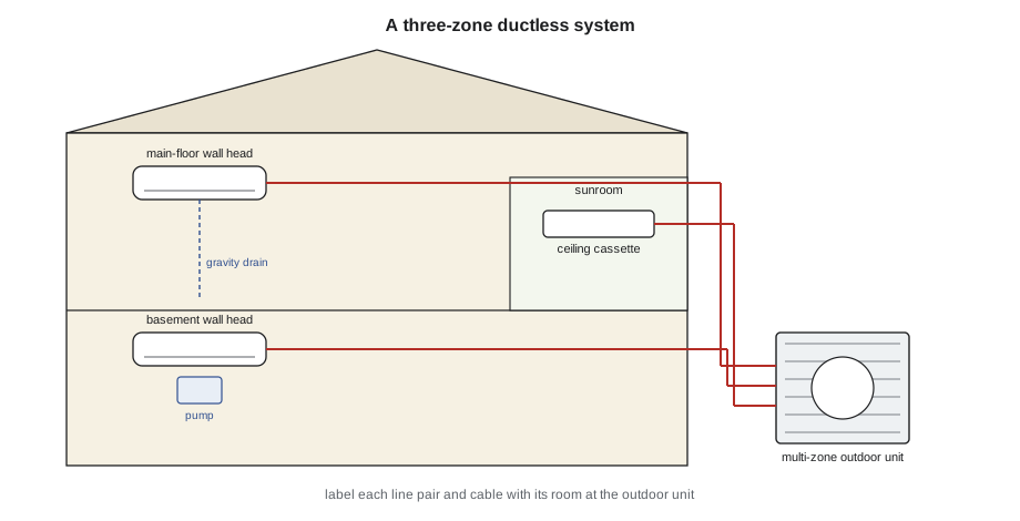
Dana and Theo walked the Haddad house with the load calculation Northfield had prepared. The main floor was open plan and needed most of the capacity. The basement family room needed modest heat and summer dehumidification. The glass sunroom at the back had large loads in both seasons. The small bedrooms upstairs, with radiators that already worked well and windows facing north, needed little cooling, and the family agreed to leave them out and rely on the open stair for some cooling from below.
Combination ratio and diversity
A multi-zone outdoor unit is usually allowed to connect indoor units whose nominal capacities add up to more than its own. The ratio of total connected indoor capacity to outdoor capacity is the combination ratio. Manufacturers publish a table of allowed combinations, often permitting ratios up to about 130 % and setting a minimum, perhaps 50 %. Ratios above 100 % work because rooms rarely all need full capacity at the same time; the sun moves, rooms are used at different times and doors are closed. That allowance is called diversity.
The catch is that when all the rooms do call at once, on a design day, the outdoor unit divides its capacity among them, and every room gets less than its head's nominal size. A high combination ratio is fine when the rooms' loads peak at different times. It is not fine when it is used to put oversized heads everywhere, or when the outdoor unit is too small for the whole house on the coldest morning. The script below checks Theo's first proposal against the manufacturer's table, the line set lengths against the installation limits, and the basement head's condensate on a humid summer day.
# The Haddads' second outdoor unit: combination ratio, line lengths and condensate
OUTDOOR = 24000                       # Btu/h nominal; ductless sizes are sold in Btu/h on both sites
proposals = {"first proposal": {"main-floor wall head": 12000, "basement wall head": 9000, "sunroom ceiling cassette": 12000},
             "revised proposal": {"main-floor wall head": 12000, "basement wall head": 9000, "sunroom ceiling cassette": 9000}}
MAX_RATIO, MIN_RATIO = 1.30, 0.50     # allowed range from the manufacturer's combination table (illustrative)
for label, heads in proposals.items():
    total = sum(heads.values())
    ratio = total / OUTDOOR
    verdict = "allowed" if MIN_RATIO <= ratio <= MAX_RATIO else "outside the manufacturer's range"
    print(f"{label}: {total:,} Btu/h of indoor heads on a {OUTDOOR:,} Btu/h outdoor unit = {ratio:.0%} -> {verdict}")
runs = {'main-floor wall head': 30, 'basement wall head': 45, 'sunroom ceiling cassette': 60}                         # line set length to each head, ft
MAX_EACH, MAX_TOTAL = 82, 165          # manufacturer's limits, ft (illustrative)
print(f"longest run {max(runs.values())} ft (limit {MAX_EACH}), total {sum(runs.values())} ft (limit {MAX_TOTAL})")
# Condensate from the basement head on a humid day: latent heat removed becomes water
LATENT = 2600                         # Btu/h of latent cooling from that head (about 760 W)
water_kg_h = LATENT / 3.412 / 1000 * 3600 / 2450        # W to kg/h with a latent heat of about 2450 kJ/kg
print(f"condensate: {water_kg_h * 2.2046:.2f} lb (about {water_kg_h * 2.2046 / 1.043:.1f} pints) of water per hour — the condensate pump must handle at least that, with a margin")first proposal: 33,000 Btu/h of indoor heads on a 24,000 Btu/h outdoor unit = 138% -> outside the manufacturer's range revised proposal: 30,000 Btu/h of indoor heads on a 24,000 Btu/h outdoor unit = 125% -> allowed longest run 60 ft (limit 82), total 135 ft (limit 165) condensate: 2.47 lb (about 2.4 pints) of water per hour — the condensate pump must handle at least that, with a margin
Theo's first proposal, a 12,000 Btu/h cassette for the sunroom, put 33,000 Btu/h of heads on a 24,000 Btu/h outdoor unit, 138 %, beyond the table. Dana pointed out that the sunroom's peak cooling load was in late afternoon, when the basement needed little, but that did not change the manufacturer's limit. With a 9,000 Btu/h cassette the ratio was 125 %, within the table, and the load calculation showed the smaller cassette could still carry the sunroom except on the hottest few afternoons. The line runs were within the per-head and total limits. The basement head would produce about 2.5 lb of water an hour on a humid day, and because the head was on an outside wall below grade, it needed a condensate pump.
Line sets and flare joints
Ductless systems use small soft copper line sets, typically 1/4 in liquid and 3/8 to 5/8 in vapor, connected with flare fittings at the indoor head and outdoor unit. The outdoor unit holds a factory charge for a stated line length; longer runs need refrigerant added by weight, as lesson 8 explains. Each manufacturer sets maximum lengths per head, a maximum total and maximum height differences between the outdoor unit and heads and between heads.
Flare joints are the most common source of leaks on ductless systems. A good flare needs the right tools and care:
- Cut the tube square with a tube cutter, never a hacksaw, and ream the burr while holding the tube downward so chips fall out, not in.
- Slide the flare nut on before flaring. It is easy to forget.
- Use a flaring tool made for refrigeration, often an eccentric cone type, and the flare dimension the manufacturer specifies, especially for A2L and R-410A systems, which often call for a slightly larger flare than older practice.
- Put a drop of the manufacturer's recommended oil on the flare's back face, not on the sealing face, if the instructions allow it.
- Tighten with two wrenches, one holding the fitting, and a torque wrench set to the manufacturer's value for that tube size. Over-tightened flares crack; under-tightened ones leak.
After the joints are made, the system is pressure tested with dry nitrogen to the manufacturer's test pressure and checked for leaks, then evacuated and checked with a decay test, as RAC-220 described. Many manufacturers now require or allow brazed connections, mechanical press fittings or reusable flare connectors for A2L systems, and some codes restrict flare joints in occupied spaces for flammable refrigerants. Theo checked the Haddad installation manual and the safety code: for the new R-454B outdoor unit, the manufacturer's flare joints were permitted at the indoor heads, with the installation's charge limits and room sizes in the manual's tables.
Power and communication
Most ductless systems feed power to the outdoor unit, which then powers each indoor head through a four-conductor interconnect cable carrying line voltage and a communication signal, as RAC-230 noted. A few feed each head separately. Because the interconnect carries line voltage, it must be the type and size the manufacturer specifies, run and protected like any other branch wiring, and disconnected before the head is opened. Communication faults on ductless systems, shown as codes on the head or the outdoor board, are often caused by a loose terminal, a wire on the wrong terminal or an interconnect spliced with the wrong connector. Lesson 5 covers communicating systems further.
Condensate
In cooling, every head produces water, and in a humid climate a lot of it. Wall heads drain through a small hose that leaves the back of the unit with the line set. The best arrangement is a gravity drain with a steady downward slope all the way to its outlet, insulated where it runs through cold spaces in winter or warm, humid spaces in summer, and ending where water can safely go. Where gravity is impossible, as in the Haddads' basement or with a head on an inside wall, a small condensate pump lifts the water. Mini pumps that fit in the line set cover are common, but they are noisy if poorly mounted, they need a safety switch wired to stop the head's cooling if they fail, and they need cleaning.
In heating mode the indoor coil is the condenser, so the heads stay dry. The outdoor unit is where water appears in winter: defrost water, as lesson 3 explained, which leaves through the base pan. It must not drain onto a walkway, a step or a driveway, where it will freeze into a hazard, and the bracket or stand must leave room under the unit for ice to form without reaching the coil.
Installation details that decide success
Ductless installations are judged by customers on things that have nothing to do with refrigeration: the neatness of the line set cover, the position of the head, the noise of the outdoor unit and the condensate pump. They are judged by technicians on the evacuation and flare joints. Both matter. Northfield's checklist for the Haddad job included: sleeve and seal every wall penetration so air, water and insects cannot enter; slope the line set and drain away from the head at the wall; use line set covers outdoors and indoors where lines are exposed; mount the outdoor unit on a bracket or stand above the snow line with vibration isolators; keep the outdoor unit away from bedroom windows and the neighbors' windows; and label each line pair and interconnect at the outdoor unit with the room it serves, because a crossed line pair and interconnect on a multi-zone system makes one room heat when another calls.
Last, the handover. Ductless heads have remote controls with modes and settings most customers have never seen. Dana always set each remote with the family: heat or cool mode, not auto, unless the room truly needed both in a day; a sensible fan setting; the louvers set to throw air where it is wanted; and filter cleaning every few weeks in the first season. "Half our ductless service calls," she told Theo, "are a remote in the wrong mode or a filter that has never been cleaned."
Common mistakes
MistakePutting the largest head that fits in every room.
InsteadSize each head from the room's load; small rooms may share a unit.
MistakeUsing a combination ratio beyond the manufacturer's table.
InsteadCheck the table, and remember every room gets less when all call at once.
MistakeMaking flares without a torque wrench.
InsteadTorque every flare to the manufacturer's value with two wrenches.
MistakeCrossing a line pair and interconnect on a multi-zone unit.
InsteadLabel each port and cable with its room and check each zone separately at start-up.
MistakeRunning condensate pumps without a safety switch.
InsteadWire the pump's overflow switch to stop cooling on that head.
Summary and key terms
- Ductless systems have an inverter outdoor unit and one or more indoor units of several styles, with no ducts.
- Single-zone systems are usually the most efficient; multi-zone systems save space and circuits.
- Heads are sized and placed room by room; oversized heads short-cycle and dehumidify poorly.
- Combination ratios above 100 % rely on diversity and must stay within the manufacturer's table.
- Flare joints need correct cutting, flaring, oil and torque, then a nitrogen test and evacuation.
- Condensate drains by gravity where possible; pumps need safety switches and cleaning.
- Mini-split
- A split system with small refrigerant lines and indoor units that need no ducts, or only short ones.
- Multi-zone
- A system with several indoor units on one outdoor unit.
- Combination ratio
- The total nominal capacity of connected indoor units divided by the outdoor unit's capacity.
- Diversity
- The allowance that not all rooms need full capacity at the same time.
- Flare joint
- A mechanical joint in which a flared tube end is clamped against a fitting by a nut.
- Interconnect cable
- The cable carrying power and communication between outdoor and indoor units.
- Condensate pump
- A small pump that lifts condensate where it cannot drain by gravity.
Practice problems
Work each problem on paper first, then reveal the answer to check.
A 24,000 Btu/h outdoor unit has heads of 9,000, 9,000 and 12,000 Btu/h. What is the combination ratio?
Show answer
30,000 ÷ 24,000 = 125 %.
Why should the flare nut go on before the tube is flared?
Show answer
Because it cannot be put on afterwards; the flare is wider than the nut's bore.
Why might one large head in a hallway be better than three small heads in three small bedrooms?
Show answer
The smallest heads may still be oversized for each bedroom, and one well-placed unit costs less and cycles less.
A basement wall head produces water but has no drain path downward. What is needed?
Show answer
A condensate pump with a safety switch, or a different head location.
Lesson quiz · 5 questions
Score 60% or more to complete this lesson.
Create a free account to save your progress, take quizzes and earn a certificate.