
RAC-320 · Lesson 10 of 12 · 18 min
Start-up and commissioning, including A2L equipment
On the second afternoon of the Novak installation, the line set had held its nitrogen test overnight, the evacuation had pulled down and held, the electrical inspector had signed off the new circuits, and the air handler and outdoor unit were wired. Marcus wanted to switch on and go. Dana had sent a start-up sheet with Theo, three pages long, and told him to fill in every line. "Starting a system and commissioning it are different things," she had said. "Starting it means it runs. Commissioning it means you have proved it does what the house needs, and written the numbers down so the next technician can compare."
This lesson covers the start-up and commissioning of residential split systems and heat pumps, including the extra steps for A2L equipment. Evacuation and charging were covered in RAC-220 and controls set-up in RAC-230; here they are put in order and connected to the house.
Before power is applied
Commissioning begins before the first start. The aim is to find faults while they are still cheap: a disconnected wire, a closed service valve or a missing filter is a nuisance before start-up and a failed compressor after it.
- Confirm the evacuation and decay test results are recorded, as RAC-220 described, and that the additional charge for the line length has been weighed in.
- Open the service valves fully, as the manual describes, and replace and tighten the valve caps, which are the final seal on many valves.
- Check the supply voltage at the disconnect and, on three-phase units, the phase rotation if the manual requires it. A scroll compressor run backwards for long will be damaged.
- Energize the crankcase heater for the time the manual gives before starting the compressor, often several hours in cold weather, so that liquid refrigerant is driven out of the oil. On the Novak unit that meant switching the disconnect on in the morning with the thermostat off.
- Check the indoor side: filters installed, blower door and panels in place, condensate trap primed and drain clear, secondary pan or float switch in place, and all supply and return registers open.
- Check the thermostat or communicating control wiring against the diagram, and the settings for the equipment type, as RAC-230 explained.
A2L equipment: the extra checks
The Novaks' heat pump, like most new equipment, used an A2L refrigerant, R-454B. A2L equipment has safety features that must be checked as part of commissioning, as RAC-220 explained for charging:
- The charge: the total system charge, including the line-length adjustment, must be within the limits the manual gives for the smallest room or space that indoor parts of the system serve or are installed in. The total is written on the unit's label.
- The refrigerant detection system: many A2L systems above a certain charge have a refrigerant sensor in the indoor unit. When it detects refrigerant, the system starts the indoor blower to dilute any leak, stops the compressor and may switch off the heater kit and other ignition sources. Commissioning includes confirming the sensor is installed and connected, and running the manufacturer's test of the mitigation sequence. A fault on this system often locks the equipment out, as the Lindqvists' chafed sensor harness did in RAC-220.
- Ignition sources and openings: the manual lists the clearances from the indoor and outdoor units to potential ignition sources and openings; they are checked once more with the installation complete.
- Labels: the A2L flame symbol and refrigerant labels on the equipment, and any labels the manual requires at the service ports and on the line set.
None of these steps changes the basic cycle. They exist because a leak of a mildly flammable refrigerant into a small, closed space could, in rare circumstances, reach a flammable concentration, and the codes and standards require several independent safeguards. Skipping them leaves the customer with equipment that does not meet its listing.
First start and airflow
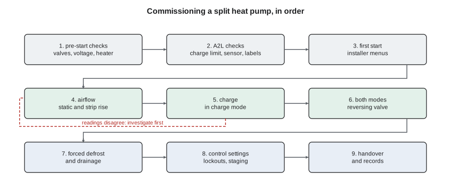
With the pre-start checks complete, the system is started in the mode that suits the weather. Many manufacturers' procedures prefer cooling for charge verification, but a heat pump started on a cold day is commissioned in heating with the manufacturer's heating procedure. Theo started the Novak system in heating, on a cool late-September afternoon. On a communicating system, the first start is usually done through the thermostat's installer menus, which also run the equipment's own self-tests and confirm the components it has found on the bus.
Airflow comes before charge, because the charge cannot be judged with the wrong airflow. Total external static pressure, measured across the air handler or furnace and compared with the blower table, gives the first check; RAC-330 covers it in detail. A second, independent check uses the heater kit itself: with the strips on and the compressor off, almost all the electrical energy going into the strips and the blower becomes heat in the air, so the airflow can be calculated from the power and the temperature rise. The power should come from measured voltage and current, not the nameplate, because heater output falls with the square of the voltage.
# Commissioning check: airflow from the temperature rise across the electric heat strips
RATED_KW, RATED_V = 10.0, 240      # heater kit nameplate
volts = 236.0                       # measured at the air handler with the strips on
amps = 40.9                          # measured total strip current
kw_volts = RATED_KW * (volts / RATED_V) ** 2       # resistance heaters: power falls with the square of voltage
kw_amps = volts * amps / 1000
blower_kw = 0.45                     # blower motor input, which also heats the air
heat_w = (kw_amps + blower_kw) * 1000
rise = 28.0                          # supply minus return, °F, measured after ten minutes
flow = heat_w * 3.412 / (1.08 * rise)
print(f"strip power: {kw_volts:.2f} kW from voltage, {kw_amps:.2f} kW from current; using {kw_amps:.2f} kW + blower")
print(f"temperature rise {rise} °F -> airflow about {flow:,.0f} cfm ({flow / 3:.0f} cfm per ton for a 3-ton system)")strip power: 9.67 kW from voltage, 9.65 kW from current; using 9.65 kW + blower temperature rise 28.0 °F -> airflow about 1,140 cfm (380 cfm per ton for a 3-ton system)
The Novak system moved about 1,140 cfm, about 380 cfm per ton, within the manufacturer's range for heating at the selected blower setting. Theo recorded the voltage, current, rise and calculated airflow, and the static pressure reading, which agreed with the blower table. Raj had told him what to look for if they disagreed: a blower table that showed much more airflow than the temperature rise suggested usually meant air was leaking around the coil or the measurement was taken where the strips did not fully mix the air.
The strip test also commissioned the heater kit: each stage came on in turn through its sequencer, each drew its expected current, and the limit switches stayed closed. The current was within a few percent of what the measured voltage predicted, so all elements were intact.
Charge verification
With airflow confirmed, the charge was verified. The Novak unit was an inverter heat pump, so Theo put it in the manufacturer's charge mode, which ran the compressor at a fixed speed in heating, and compared the liquid subcooling at the indoor coil with the manufacturer's heating chart for the measured outdoor and indoor temperatures, as RAC-220 described. It was within the chart's band. Because the charge had been weighed in for the measured line length, a large difference would have pointed to a measurement error, a restriction or a leak, not a reason to add or remove refrigerant without investigating.
Many manufacturers ask for the charge to be checked again in cooling at the first suitable opportunity, especially when the start-up is in cold weather. Theo put a reminder in Northfield's system for a cooling check in early summer, at the first maintenance visit.
Checking both modes and defrost
A heat pump must be proved in both modes, whatever the season. Theo switched the thermostat to cooling and confirmed the reversing valve shifted cleanly, the large line at the indoor coil turned cold and the supply air dropped, then switched back to heating and confirmed the reverse. On a cool day the cooling run was short, enough to prove the valve and the indoor coil's drainage, not to measure performance.
Defrost was tested with the manufacturer's test function, which forces a defrost on demand. Theo watched the sequence from lesson 3: the reversing valve shifted, the outdoor fan stopped, the first stage of strips came on to temper the air, the coil warmed and the valve shifted back on the timed test. He also checked that the base pan heater was energized and that water from the coil drained freely off the stand.
Setting the controls for the house
The last part of commissioning is making the system behave the way the house and the family need. On the Novak communicating thermostat, Theo set, with Dana's notes:
- The heat pump's low-ambient lockout at the manufacturer's recommended value, so the unit would protect itself in extreme cold.
- The auxiliary heat lockout, so the strips could not run above a mild outdoor temperature except in defrost and emergency heat, as lesson 3 explained.
- The backup heat's staging delays, so the first stage came on only after the heat pump had been running at full speed for a while without satisfying the setpoint.
- The airflow profile and dehumidification setting for cooling, for the summer.
- A gentle setback schedule, with an early start and a small step, because deep setbacks on a heat pump bring on the strips every morning.
Each setting was recorded on the start-up sheet. A system that runs with the wrong lockouts and staging can cost the family hundreds of dollars a year without any fault ever appearing.
Handover
Commissioning ends with the customer. The Novaks had used a furnace all their lives; a heat pump behaves differently, and a few minutes of explanation prevents most first-winter calls. Theo walked Irene and Pavel through the thermostat, then explained:
- that the supply air would feel cooler than the furnace's, as lesson 2 described, while still heating the house;
- that the outdoor unit would sometimes steam and whoosh during defrost, and the fan would stop for a few minutes;
- that on the coldest mornings the strips would help, and the thermostat would show it;
- how to switch to emergency heat if the heat pump ever failed, and to call Northfield if they did;
- how to keep the outdoor unit clear of snow and leaves, and how often to change the filter.
He left the start-up sheet, the AHRI certificate, the warranty registration instructions and the manuals in a folder by the air handler, and uploaded the same records to the job file. The Novaks' incentive application needed several of them, and Irene had a checklist ready.
When start-up readings do not agree
Commissioning is the moment when problems are cheapest to find, so readings that do not agree with each other or with the manual are investigated before the crew leaves. On an earlier job, Theo had seen what happens otherwise. The static pressure on a new system had been high, the temperature rise in heating had been high too, and the airflow calculated from the strips was well below the blower table's value. The crew had left anyway, assuming the strips were reading wrong. Three weeks later the customer called with a system tripping on high pressure every cold morning. The cause was a return duct crushed behind a finished wall during the renovation, exactly what the start-up readings had shown.
Raj's rule for start-ups was that every measured value should agree with at least one other: airflow from static pressure with airflow from temperature rise, subcooling with the weighed charge, compressor current with the manufacturer's table at the measured conditions, supply temperature with the expected capacity. When two values disagree, one of them is wrong or something in the system is, and finding out which is part of the job.
Common mistakes
MistakeStarting the compressor without energizing the crankcase heater first in cold weather.
InsteadEnergize it for the time the manual gives before the first start.
MistakeJudging the charge before confirming airflow.
InsteadConfirm airflow by static pressure and, where possible, by heat strip rise.
MistakeUsing the heater kit's nameplate rating for the airflow calculation.
InsteadUse measured voltage and current; output falls with the square of voltage.
MistakeSkipping the refrigerant detection system test on A2L equipment.
InsteadRun the manufacturer's mitigation test and record it.
MistakeLeaving the thermostat's lockouts and staging at default.
InsteadSet them for the house and record them.
Summary and key terms
- Commissioning proves the system does what the house needs and records the numbers.
- Pre-start checks cover evacuation records, valves, voltage, crankcase heater time, indoor drains and wiring.
- A2L equipment adds checks of charge limits, the refrigerant detection system, clearances and labels.
- Airflow comes before charge; heat strip temperature rise with measured power gives an independent check.
- Inverter units are charged and verified in the manufacturer's fixed-speed mode.
- Both modes, defrost and control settings are tested, and the customer is shown how the system behaves.
- Commissioning
- Verifying and documenting that a system is installed and set up to meet its design intent.
- Crankcase heater
- A heater that keeps refrigerant from condensing in the compressor oil while it is off.
- Refrigerant detection system
- Sensors and controls in A2L equipment that detect a leak and start mitigation.
- Mitigation
- The actions an A2L system takes on detecting a leak, such as running the blower and stopping ignition sources.
- Temperature rise
- The difference between supply and return air temperatures in heating.
- Charge mode
- A manufacturer's fixed-speed test mode used for charging and verification.
- Handover
- Explaining the system to the owner and leaving the records.
Practice problems
Work each problem on paper first, then reveal the answer to check.
A 10 kW heater kit rated at 240 V is measured at 230 V. What is its output?
Show answer
10 × (230 ÷ 240)² = about 9.2 kW.
With 9.8 kW of strip and blower heat and a 30 °F rise, what is the airflow?
Show answer
9,800 × 3.412 ÷ (1.08 × 30) = about 1,030 cfm.
Why is a heat pump started on a cold day not charged with the cooling chart?
Show answer
The cooling chart applies to cooling conditions; the manufacturer's heating procedure or weigh-in is used.
Name two things an A2L refrigerant detection system may do when it senses a leak.
Show answer
Any two of: start the indoor blower, stop the compressor, switch off the heater kit or other ignition sources, show a fault.
Lesson quiz · 5 questions
Score 60% or more to complete this lesson.
Create a free account to save your progress, take quizzes and earn a certificate.