
RAC-320 · Lesson 12 of 12 · 18 min
Troubleshooting heat pumps and the Novak retrofit capstone
By the end of the Novaks' first winter with their heat pump, Theo had been back to the house twice and had taken a third heat pump call across town at the Ruiz house. None of the calls was complicated, but each one needed the whole course: the balance point, defrost, airflow, controls, installation details and a methodical approach. This last lesson sets out how to troubleshoot heat pumps and then follows those three calls, before looking at what the Novaks' conversion actually achieved.
A method for heat pump calls
Heat pump complaints come in a few forms: not enough heat, high bills, ice on the outdoor unit, noise, cold air from the registers or a system that will not run. Raj's method for all of them started away from the equipment.
- Listen to the complaint and find out when it happens: all the time, on cold mornings, after a defrost, since a renovation, since a power failure.
- Check the thermostat: mode, setpoint, emergency heat, the outdoor temperature it reads, its lockouts and its recent history. On communicating systems, read the fault history first, as lesson 5 explained.
- Decide what the system should be doing at today's outdoor temperature, from the balance point and the capacity data. A heat pump that cannot keep the house warm at −13 °F may be normal; one that cannot at 40 °F is not.
- Check the air side before the refrigerant side: filters, returns, registers, blower, static pressure, temperature rise. Many heating complaints are airflow problems.
- Check the outdoor unit: ice, snow, drainage, clearances, fan, and whether it is in heating, defrost or off.
- Only then measure the refrigerant side, in the manufacturer's test mode on inverter units, and compare with the start-up record.
Reversing valve faults
The reversing valve has three common faults. Its solenoid coil can fail, open or burned, so the valve stays in its unenergized position: heating on most North American systems. Its pilot or slide can stick, so it does not shift or shifts only partway. Or the slide can leak internally, letting hot discharge gas bypass straight to the suction, which looks like a weak compressor: low discharge pressure, high suction pressure, low capacity and high current for the output.
Diagnosis starts electrically. With the thermostat calling for the mode that energizes the valve, the coil should have its rated voltage across it, and a steel screwdriver held near it should feel the magnetic pull. A coil with voltage and no pull is open; no voltage points to the thermostat, wiring or board. If the coil is good, line temperatures tell the rest. In heating, the line from the valve to the indoor coil should be hot and the line from the outdoor coil to the valve cold, and the suction line from the valve to the compressor should be cold, close to the outdoor coil's outlet temperature. A suction line that is warm, or noticeably warmer than the outdoor coil outlet, means hot gas is leaking across the slide. Shifting the valve back and forth a few times with the system running sometimes frees a sticking slide; a leaking slide must be replaced.
Replacing a reversing valve is a brazing job close to a part that heat can ruin. The refrigerant is recovered, the valve body is wrapped in a wet cloth or heat-absorbing paste, the joints are brazed under a nitrogen purge, as RAC-210 described, and the new filter-drier, pressure test, evacuation and weighed charge follow, as RAC-220 described.
Low heat in cold weather
The most common winter complaint is not enough heat. The causes, roughly in order of how often Raj found them, were: expectations, where the system was working normally below its balance point but the customer expected furnace-hot air; controls, such as an auxiliary heat lockout set too low, a failed outdoor sensor or a thermostat in the wrong mode; airflow, from filters, blocked returns or a failed blower setting; the outdoor unit, iced, buried in snow or with its fan or defrost not working; the backup heat, with a tripped breaker, an open limit or a failed sequencer; and finally the refrigerant circuit itself, with low charge, a restriction, a reversing valve fault or a compressor problem. Starting at the top of the list saves a great deal of time.
Call 1: ice under the Novak unit
In December, a week after a heavy wet snowfall, Pavel Novak sent a photograph: the outdoor unit's base was sitting in a block of ice, and ice was creeping up the bottom of the coil. The house was still warm, but the strips were running more than usual. Theo arrived to find the cause before he touched the unit. The eavestrough contractor who had replaced the gutters in November had added a downspout on the side wall, and its extension discharged onto the gravel under the heat pump's stand. Every thaw and every defrost had added water to the same spot, and every cold night had frozen it.
Theo started a forced defrost and then ran the unit in heating with the fan, letting the coil clear; he melted the ice under the base with warm water rather than chipping it, as lesson 3 required. The fix was outside the heat pump: the downspout extension was redirected away from the unit, and the gravel bed was raked level so defrost water could drain away. He checked the base pan heater, which was working, and the drain holes, which were clear once the ice was gone, and noted on the Novaks' record to check the area at each winter visit. The placement decision in lesson 8 had been right; the house had changed around it.
Call 2: a cold snap at the Novaks'
In late January, a cold snap brought the coldest night of the winter, about −9 °F. The Novaks called in the morning: the house was two degrees below the setpoint and the registers felt cool. Theo checked the thermostat first. The outdoor temperature reading agreed with the forecast, the heat pump was running at full speed and both stages of strips were on, and there were no faults. At that temperature the heat pump was expected to deliver well under the house's load, as lesson 6 showed, so strips were expected; but the house should still have held its setpoint, because the heater kit was sized for full emergency heat.
The air side showed the problem. The total external static pressure was far above the start-up record. The filter was loaded, more than Theo expected at that point in the season, and the new return grille in the basement family room was hidden behind a sofa that had been moved for the holidays. With the airflow reduced, the strips were cycling on their limit switches, and the heat pump's condensing pressure was climbing, so its controller was slowing it down to protect itself. Theo replaced the filter, moved the sofa with the Novaks' help, and watched the static pressure return to its start-up value, the strips stop cycling and the supply temperature rise. By early afternoon the house was back at its setpoint. He suggested a filter check every month in winter and showed the Novaks how to read the static pressure warning their thermostat could display.
Call 3: a weak heat pump at the Ruiz house
The Ruiz heat pump from lesson 3 was twelve years old. In February, Mrs. Ruiz called because the strips seemed to run all the time, even on mild days. Theo checked the thermostat: the lockout was still set as he had left it, and the outdoor temperature was 36 °F, well above the balance point. The heat pump was running but the supply air temperature rise was only about half the value in the start-up and maintenance records, so the thermostat was calling auxiliary heat to make up the difference.
The air side was fine: static pressure matched the record and the filter was clean. At the outdoor unit, the coil was clear and the fan running. Theo connected gauges with low-loss fittings. The discharge pressure was low for the conditions and the suction pressure high, and the compressor current was higher than the record for the output it was giving. The pattern fitted either a worn compressor or a leaking reversing valve. The line temperatures settled it: the suction line between the reversing valve and the compressor was much warmer than the outdoor coil's outlet line. Hot gas was leaking across the slide inside the valve.
The quote for a new reversing valve, a filter-drier and the labor was a substantial fraction of a new system's price on a twelve-year-old R-410A heat pump, so Dana gave Mrs. Ruiz both options. She chose the repair, because the compressor was healthy and the rest of the system in good condition. Raj and Theo replaced the valve the following week, with the brazing done under nitrogen and the valve body kept cool, and the system returned to its recorded performance.
The Novak conversion after one winter
In April, Irene Novak sent Dana the household's energy records and asked whether the conversion had done what the load calculation and the selection said it would. Theo compared them with the estimate Northfield had made for the quote, which the script below reproduces: the annual heat needed from the heat loss and the heating degree-days, the fuel the old furnace would have used and the electricity the heat pump would use at a seasonal COP that includes defrost and strip heat.
# Novak house: annual heating energy and cost, old furnace versus the cold-climate heat pump
UA = 500                    # Btu/h per deg F, from the heat loss calculation
HDD = 4300                    # heating degree-days (deg F days), typical for Louisville
CORR = 0.80                  # degree-day correction for internal gains and solar heat (typical)
heat = UA * HDD * 24 * CORR / 1e6             # MMBtu of heat delivered per year
print(f"heat needed: {heat:,.1f} MMBtu per year")
FUEL_NAME, FUEL_PRICE, FUEL_CONTENT, FURNACE_EFF = "propane", 2.75, 0.0915, 0.8
fuel = heat / (FUEL_CONTENT * FURNACE_EFF)
print(f"old furnace: {fuel:,.0f} gal of {FUEL_NAME} at {FURNACE_EFF:.0%} -> {fuel * FUEL_PRICE:,.0f} dollars per year")
SCOP, ELEC = 2.9, 0.14               # seasonal COP including defrost and strip heat; dollars per kWh
kwh = heat * 1e6 / 3412 / SCOP
print(f"heat pump: {kwh:,.0f} kWh at a seasonal COP of {SCOP} -> {kwh * ELEC:,.0f} dollars per year")
print(f"difference: {fuel * FUEL_PRICE - kwh * ELEC:,.0f} dollars per year at these prices")heat needed: 41.3 MMBtu per year old furnace: 564 gal of propane at 80% -> 1,551 dollars per year heat pump: 4,172 kWh at a seasonal COP of 2.9 -> 584 dollars per year difference: 967 dollars per year at these prices
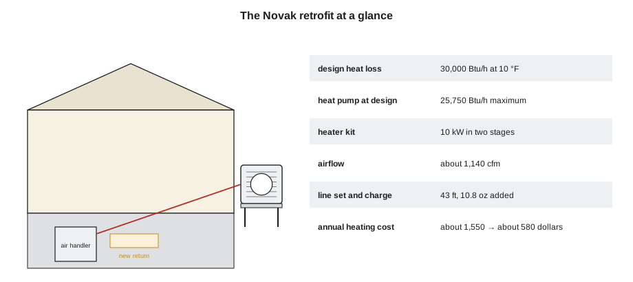
The estimate was about 41 MMBtu of heat a year. The old furnace would have needed about 560 gallons of propane, close to what the Novaks had actually bought in a typical year, at a cost of about 1,550 dollars at the prices used. The heat pump would use about 4,200 kWh of electricity, about 580 dollars. The Novaks' meter showed about 4,500 kWh of extra electricity over the winter, a little more than the estimate, because the winter had been colder than average and the cold snap had used more strip heat. Even so, the family's heating cost had fallen by more than half, and the propane tank was gone. They also had air conditioning for the first time in years.
Theo noticed how many of the numbers in that result went back to decisions earlier in the course: the air sealing that lowered the load in lesson 7, the cold-climate unit chosen from its maximum capacity in lesson 6, the stand that kept it above the snow in lesson 8, the lockout and staging settings that kept the strips for the coldest hours in lessons 3 and 10, and the airflow that call 2 had restored. A heat pump retrofit is judged by the family's comfort and their bills, and those depend on every step.
What comes next
With RAC-320 complete, Theo's next course would go deeper into the air side: psychrometrics, heating and cooling loads, airflow measurement, duct systems and ventilation in RAC-330. Dana's advice as he finished his season on the comfort side was the same as at the start: "The refrigeration is the same. The house, the family and the airflow are what you'll spend your career learning."
Common mistakes
MistakeStarting a heat pump diagnosis at the gauges.
InsteadStart with the complaint, the thermostat, the expected behavior and the air side.
MistakeCondemning a compressor without checking the reversing valve.
InsteadCompare the suction line temperature after the valve with the outdoor coil outlet; a warm suction line means valve bypass.
MistakeTreating strip heat on the coldest night as a fault.
InsteadCheck whether the temperature is below the balance point; then check the backup heat works as designed.
MistakeFixing ice on an outdoor unit without finding the water source.
InsteadLook for roof water, downspouts and blocked drainage first.
MistakeBrazing a reversing valve without protecting its body.
InsteadWrap it in a wet cloth or heat paste and braze under nitrogen.
Summary and key terms
- Heat pump troubleshooting starts with the complaint, the thermostat and what the system should do at today's temperature.
- Air side problems cause many low-heat complaints and should be checked before refrigerant readings.
- Reversing valve faults are found by checking the coil electrically, then comparing line temperatures.
- Ice on an outdoor unit usually has a water source or drainage cause outside the unit.
- The Novak conversion cut the family's heating cost substantially, close to the estimate, because each step of the course was done carefully.
- Records from commissioning and maintenance make every later diagnosis faster.
- Valve bypass
- Internal leakage of hot gas across a reversing valve's slide to the suction.
- Seasonal COP
- The average COP over a heating season, including defrost and backup heat.
- Heating degree-day
- A measure of how cold a period was, summing the daily shortfall of outdoor temperature below a base temperature.
- Low-loss fitting
- A hose fitting that limits refrigerant loss when gauges are connected or removed.
- Static pressure warning
- A thermostat or control alert that airflow resistance has risen above a set limit.
- Low heat complaint
- A customer report that the house will not reach or hold its setpoint.
Practice problems
Work each problem on paper first, then reveal the answer to check.
A heat pump in heating has low discharge pressure, high suction pressure and a warm suction line between the reversing valve and the compressor. What is the most likely fault?
Show answer
Hot gas leaking across the reversing valve's slide.
A thermostat calls for cooling on a system that energizes the valve in cooling, but the unit heats. The coil has rated voltage but no magnetic pull. What is wrong?
Show answer
The reversing valve's solenoid coil is open.
Using the Novak figures, how much electricity would a seasonal COP of 3.2 save compared with 2.9?
Show answer
12,100 ÷ 2.9 − 12,100 ÷ 3.2 = about 390 kWh a year.
Name three causes of low heat in cold weather to check before the refrigerant circuit.
Show answer
Any three of: expectations below the balance point, thermostat or lockout settings, airflow, outdoor unit ice or snow, backup heat faults.
Lesson quiz · 5 questions
Score 60% or more to complete this lesson.
Create a free account to save your progress, take quizzes and earn a certificate.