
RAC-120 · Lesson 7 of 12 · 17 min
Recovery equipment, hoses and connections
Northfield's newest recovery machine sat on the shop bench with its covers off. Dana had bought it to replace an older machine that could not be used on A2L refrigerants, and she used the opportunity to show Theo what was inside: a small oil-less compressor, a finned condenser with a fan, a filter-drier at the inlet, a pressure switch, a few valves and a lot of copper tube. "It is just a refrigeration system with no evaporator," she said. "It pulls refrigerant out of the system you're working on, condenses it, and pushes it into the cylinder. Everything we do in recovery is about helping it do that quickly and cleanly."
This lesson covers the equipment of refrigerant recovery: the terms recover, recycle and reclaim; how recovery machines work and how they are certified; system-dependent recovery; hoses, fittings, valves and access devices; and how to set up for a recovery job. Lesson 8 then covers the methods: vapor, liquid and push-pull recovery.
Recover, recycle, reclaim
Three words are used precisely in the regulations and on the exam.
- To recover is to remove refrigerant from a system, in any condition, and store it in an external container, without necessarily testing or processing it.
- To recycle is to clean refrigerant for reuse, usually by separating oil and passing it repeatedly through filter-driers that remove moisture, acid and particles. Recycling is done on the job or in the contractor's shop, and recycled refrigerant may normally be returned only to equipment of the same owner.
- To reclaim is to reprocess refrigerant to the purity of new product, set by the standard AHRI 700, and to verify that purity by chemical analysis of each batch. Reclaiming is done by a licensed or certified reclaimer in a dedicated facility, and reclaimed refrigerant may be sold to anyone.
Most service companies recover, some recycle, and almost none reclaim. In both countries the default for recovered refrigerant that will not go back into the same owner's equipment is to send it to a reclaimer, which Lesson 12 covers.
How a recovery machine works
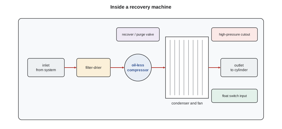
A self-contained recovery machine, sometimes called active recovery equipment, has its own compressor. Refrigerant enters through the inlet, passes through a filter or filter-drier that protects the compressor from debris and moisture, and is compressed. The hot discharge gas passes through the machine's condenser, where a fan removes heat and condenses it, and then leaves through the outlet to the recovery cylinder as liquid or a mixture of liquid and gas. A high-pressure switch stops the compressor if the outlet pressure rises too high, for example because the cylinder valve is closed or the cylinder is too hot. Most machines have a connection for a cylinder float switch that stops the compressor at the fill limit.
Modern machines use oil-less compressors, which avoid the problem of oil being carried out of the machine into the recovery cylinder and of one refrigerant's oil contaminating the next. Many machines can handle liquid directly, using a metering valve or a compressor design that tolerates liquid; others need liquid to be throttled at the inlet. When the system has been pulled down to the required vacuum, the machine's purge or self-clear mode pumps the refrigerant left inside the machine and its hoses into the cylinder, so that it is not lost when the hoses are disconnected and does not contaminate the next job.
The performance of a recovery machine is given as rates for vapor, liquid and push-pull recovery, in pounds per minute, measured under standard conditions. Real rates on the job are often much lower, because of hose restrictions, cold system temperatures, hot cylinders and long line sets.
Certified recovery equipment
EPA requires recovery and recycling equipment used on stationary equipment to be certified by an EPA-approved testing organization as meeting its standards, normally by testing to AHRI 740, which measures how deeply the machine can evacuate a system, how fast it recovers, how much refrigerant it releases during use and, for recycling equipment, how well it cleans the refrigerant. Certified machines carry a label saying so. Equipment for A2L and A3 refrigerants must also be designed and listed for flammable refrigerants, typically under the safety standard UL 1963. Equipment manufactured before EPA's certification program began may be grandfathered if it met the earlier requirements.
Equipment for different refrigerants can differ in important ways. A machine for high-pressure refrigerants such as R-410A must handle high discharge pressures. A machine for flammable refrigerants must avoid sparks: its switches, motor and fan are designed so that a leak of flammable refrigerant into the machine cannot be ignited. Using a machine outside its rating, such as recovering R-32 with a machine not listed for A2L refrigerants, creates a fire risk and may also break the rules.
Low-pressure chillers, which run below atmospheric pressure on the low side, need recovery equipment designed for them, often a large machine that removes liquid first and then pulls vapor, with water-cooled condensers and a heater to boil off refrigerant trapped in the oil and the chiller barrel. Those machines are covered with chillers later in the program.
System-dependent recovery
System-dependent, or passive, recovery uses the system's own compressor, or its own pressure, to move refrigerant into a recovery container, without a recovery machine. A common example is a small appliance whose compressor still runs: with a recovery bag or an evacuated container connected, running the compressor pushes refrigerant out. If the compressor does not run, the technician may warm and tap the compressor to release refrigerant dissolved in its oil, and open both the high and low sides to the container.
EPA allows system-dependent recovery equipment only on appliances with a full charge of 15 pounds or less, which in practice means small appliances and small air conditioning systems, unless it is a permanently attached pump-out unit. It is common for Type I work on refrigerators and window units, and its limits are the reason the rules favor self-contained equipment: it cannot reach a deep vacuum, it depends on the condition of the system, and if the compressor does not run, both sides of the system must be accessed to recover enough refrigerant to meet the required level.
Hoses and fittings
Recovery speed is limited more often by hoses than by the machine. Refrigerant flow through a hose depends very strongly on its inside diameter and length: a hose half the diameter passes only a small fraction of the flow. The standard 1/4 inch charging hoses on a manifold set were designed for charging and gauge readings, not for moving large amounts of refrigerant. For recovery, use the shortest practical hoses, of 3/8 inch diameter where the equipment allows.
Every hose used for recovery should have a low-loss fitting or a shut-off valve at the end that connects to the system, so that refrigerant trapped in the hose is not released when it is disconnected. Ball valves at the hose ends are the most common choice. Low-loss fittings close automatically when disconnected. Hoses must also be rated for the refrigerant's pressure, and for evacuation they must be vacuum rated: ordinary charging hoses can let air in through their walls and gaskets when they are under deep vacuum.
The biggest single restriction is usually the Schrader valve core in the system's access port, a spring-loaded valve like a tire valve. Its tiny passage and the depressor in the hose fitting slow recovery dramatically. A valve core removal tool, which attaches to the port, lets the technician unscrew and withdraw the core under pressure, recover through the open port, and reinstall the core afterwards without releasing refrigerant. On a typical residential system, removing the cores and using larger hoses can cut recovery time by more than half.
# Rough comparison of recovery time with different setups (vapor recovery, lb)
# Effective rates are illustrative field values, not machine ratings.
charge_lb = 8.0          # residential R-410A split system
setups = {
    "1/4 in hoses through Schrader cores": 0.22,     # lb per minute, effective
    "1/4 in hoses, cores removed":         0.40,
    "3/8 in hoses, cores removed":         0.66,
    "liquid recovery first, then vapor":   1.76,     # average over the job
}
for name, rate in setups.items():
    minutes = charge_lb / rate
print(f"{name:38s} about {minutes:5.0f} minutes")1/4 in hoses through Schrader cores about 36 minutes 1/4 in hoses, cores removed about 20 minutes 3/8 in hoses, cores removed about 12 minutes liquid recovery first, then vapor about 5 minutes
The numbers are illustrative, but the pattern matches what technicians see: the setup decides the time. Theo's first recovery through two charging hoses and the system's valve cores took most of an hour on a job that Dana's setup finished in a quarter of the time.
Access devices
Refrigerant is reached through the system's service valves or access ports. Larger systems have service valves with a stem that can be turned to open or close a gauge port; split systems have liquid and suction service valves at the outdoor unit; many systems have Schrader access ports on the lines. Small appliances such as refrigerators often have no access port at all. For these, a piercing valve, also called a line tap or saddle valve, is clamped onto the process tube and a needle pierces it to give access.
Piercing valves are meant for temporary use. They should be used on the soft copper or aluminum process tube, tightened carefully so they seal, and removed after the job, with the tube pinched and brazed or fitted with a permanent access fitting if the system will stay in service. A piercing valve left on a system is a common long-term leak point. On a system that is being scrapped, two piercing valves, one on the high side and one on the low side, help recover refrigerant when the compressor does not run.
Before connecting to any system, check the refrigerant type, confirm the access points, and make sure every hose is purged of air. Air in a recovery hose ends up in the recovery cylinder as a non-condensable gas, raising the cylinder pressure and contaminating the refrigerant.
Setting up for a recovery job
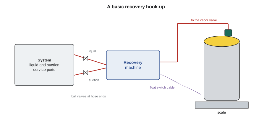
Dana's checklist for a recovery job is pinned inside every van door:
- Identify the refrigerant and check whether the equipment is rated for it, including A2L or A3 if needed.
- Choose a recovery cylinder dedicated to that refrigerant, rated for its pressure, within its retest date, evacuated if empty, and with room for the charge. Put it on the scale and connect the float switch.
- Check the recovery machine: correct mode, clean inlet filter, purged of the last refrigerant, and in good condition.
- Use the shortest, largest hoses available, with ball valves or low-loss fittings, and remove valve cores where possible.
- Purge air from the hoses with a small amount of the system's own refrigerant through the connections, or evacuate the hoses before opening them to the system.
- For flammable refrigerants, check the area with a suitable detector, control ignition sources and ventilate.
- Wear safety glasses and gloves, and stay with the machine while it runs.
Recovering into a cold cylinder speeds the job, because a cold cylinder has a lower pressure for the machine to push against. In summer, some technicians set the cylinder in a bucket of cool water or ice water; never heat a recovery cylinder, and never let a cylinder sit in the sun during recovery.
Common mistakes
MistakeUsing the manifold's charging hoses and leaving the valve cores in for a large recovery.
InsteadUse short, large hoses with cores removed; the setup decides the time.
MistakeRecovering an A2L refrigerant with a machine not listed for it.
InsteadUse equipment designed and listed for the refrigerant's flammability class.
MistakeDisconnecting hoses without closing the hose-end valves.
InsteadClose ball valves or low-loss fittings first so trapped refrigerant is not released.
MistakeLeaving a piercing valve on a refrigerator that stays in service.
InsteadRemove it and seal the process tube permanently.
MistakeSkipping the purge at the end of recovery.
InsteadRun the machine's purge or self-clear mode so the refrigerant inside it goes into the cylinder.
Summary and key terms
- Recover means remove and store; recycle means clean for reuse in the same owner's equipment; reclaim means process to AHRI 700 purity with chemical analysis.
- A recovery machine is a compressor and condenser, protected by an inlet filter and a high-pressure switch, with a purge mode and a float switch connection.
- Recovery equipment is tested to AHRI 740; equipment for flammable refrigerants must be listed for them.
- System-dependent recovery is limited to small systems and cannot reach a deep vacuum.
- Hose diameter, hose length and valve cores decide recovery speed; use low-loss fittings or ball valves.
- Piercing valves are temporary; set up with a dedicated, weighed cylinder and a connected float switch.
- Recover
- Remove refrigerant and store it in an external container.
- Recycle
- Clean refrigerant for reuse, usually by oil separation and filter-driers.
- Reclaim
- Reprocess refrigerant to AHRI 700 purity and verify it by chemical analysis.
- Self-contained recovery
- Recovery with a machine that has its own compressor.
- System-dependent recovery
- Recovery using the system's own compressor or pressure.
- Low-loss fitting
- A hose fitting that closes when disconnected to limit refrigerant loss.
- Valve core removal tool
- A tool that removes and replaces a Schrader core under pressure.
- Piercing valve
- A temporary clamp-on valve that pierces a process tube for access.
- AHRI 740
- The performance standard for refrigerant recovery and recycling equipment.
Practice problems
Work each problem on paper first, then reveal the answer to check.
What is the difference between recycling and reclaiming?
Show answer
Recycling cleans refrigerant for reuse, normally in the same owner's equipment; reclaiming reprocesses it to AHRI 700 purity with verification by chemical analysis.
Why do modern recovery machines use oil-less compressors?
Show answer
To avoid carrying oil into the cylinder and cross-contaminating refrigerants between jobs.
Give two ways to speed up vapor recovery on a residential system.
Show answer
Remove the Schrader cores, use short large-diameter hoses, recover liquid first, keep the cylinder cool.
Why must hoses be purged before recovery?
Show answer
Air in the hoses would enter the recovery cylinder as a non-condensable gas.
Lesson quiz · 5 questions
Score 60% or more to complete this lesson.
Create a free account to save your progress, take quizzes and earn a certificate.