
PWR-320 · Lesson 4 of 12 · 23 min
Lubrication and seal oil systems
▶ Video coming soon A video version of this lesson is on the way.
Every bearing on Keswold's steam turbine and generator had been opened during the outage, so before the rotor could turn again under its own weight the whole lubricating oil system had to be flushed clean. On Monday, October 5, 2026, Okonkwo spent the day with Liesl Brannagan and two of Keswold's mechanics at the oil tank, where a temporary flushing pump and a bank of fine filters had been connected. Fine mesh screens sat in the oil supply to every bearing, and the bearings themselves had been bypassed with temporary jumper hoses so that flushing oil could run at much higher velocity than normal without washing dirt into them.
"If you want to wreck a turbine cheaply," one of the mechanics said, "leave a handful of grinding grit in the oil." The screens were pulled and examined every few hours; at the first check of the morning the screen from bearing 2 held a few flakes of weld spatter from a pipe repair. The flush would go on until the screens stayed clean and a laboratory particle count met the manufacturer's target.
This lesson explains the jobs a turbine oil system does, follows the oil from the tank to the bearings and back, describes the pumps and their automatic starting, the coolers, filters and purifiers, and the oil itself and how its condition is tested. It then describes the seal oil system that keeps hydrogen inside a hydrogen-cooled generator, and the precautions against oil fires.
What the oil does
A turbine generator's lubricating oil has four jobs. It forms the oil film that carries the rotor in its journal bearings and the thrust collar against its pads; it carries away the heat generated in those films by shearing the oil, which on a machine of Keswold's size amounts to well over 340,000 Btu/h; it lifts the rotor off the bottom of its bearings for turning gear operation, through a separate high-pressure jacking oil system; and on many turbines it also supplies the turning gear's lubrication and the couplings. On older turbines and many mechanical drives the same oil also operates the governor and trip system. On a hydrogen-cooled generator a related oil system also seals the hydrogen in.
Losing the oil supply to a turning rotor destroys its bearings within seconds. The white metal lining melts and smears, the rotor drops onto the steel backing, and the journal is scored. That is why the oil system has more automatic backup than almost any other system in the plant.
The oil circuit
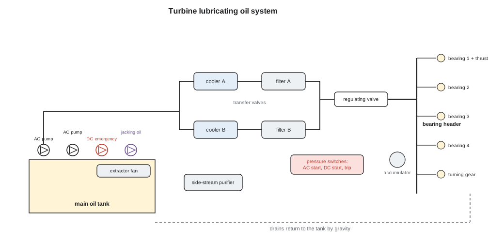
The main oil tank, or reservoir, sits below the turbine floor so that oil drains back to it from the bearings by gravity. It is large enough to let air and water separate from the oil and to hold the whole system's contents during a shutdown. A vapor extractor fan on top of the tank holds a slight vacuum in the tank and the drain lines, pulling oil mist out through a separator so that it does not escape along the shaft at the bearing seals.
- Pumps draw oil from the tank and deliver it through coolers and filters to a bearing header, from which each bearing takes its supply through an orifice that sets its flow.
- A pressure regulating valve holds the bearing header pressure, typically in the order of 15 to 25 psi above atmospheric, returning surplus oil to the tank.
- Oil leaves the coolers at a controlled temperature, typically 105 to 120 °F, and returns from the bearings perhaps 25 to 35 °F hotter. Sight glasses or flow indicators in each bearing drain let operators see oil returning.
- Bearing metal temperatures are measured by thermocouples or RTDs embedded in the white metal near the loaded part of each bearing and in the thrust pads; they are the most direct warning of a failing oil film. Alarms are typically set somewhere around 220 to 240 °F, with trips higher, as the manufacturer specifies.
Pumps and their backups
On many turbines the main oil pump is a centrifugal pump driven from the turbine shaft itself, so that at speed it supplies oil whenever the rotor is turning; it cannot supply oil at low speed or when the turbine is stopped. Other turbines, including Keswold's, use two full-capacity motor-driven pumps instead. Either way, the arrangement of backups follows the same pattern:
- An AC auxiliary oil pump runs during startup and shutdown, when a shaft-driven pump cannot deliver enough, and starts automatically if the header pressure falls.
- A DC emergency oil pump, powered by the station battery, starts automatically if the header pressure falls further. It is sized to carry the bearings through a coast-down and turning gear operation when all AC power is lost, which is exactly when it will be needed.
- An accumulator or an elevated rundown tank on some machines carries the header through the few seconds it takes a standby pump to start.
- A jacking oil pump, a small high-pressure positive displacement pump, delivers oil to pockets in the bottom of the journal bearings to lift the rotor on a film of oil when it is turning slowly or starting, because at turning gear speed the rotor cannot generate its own oil film.
The automatic starts are controlled by pressure switches on the bearing header, set in steps: the AC auxiliary pump first, then the DC emergency pump, then, if pressure keeps falling, a low lubricating oil pressure trip that shuts the turbine down. The turning gear is interlocked so that it cannot start without lubricating and jacking oil pressure. Because the backups only matter if they work when called, the pressure switches and pump starts are tested regularly, usually by bleeding pressure from each switch through a test valve while watching the pump start; lesson 6 describes how Keswold did this before its startup.
If AC power is lost while the turbine is coasting down, the DC pump must keep running until the rotor has stopped and, if possible, the turning gear has been restored or the rotor turned by hand at intervals. Operators also break vacuum in an emergency coast-down, opening a vacuum breaker valve on the condenser so that the air entering the exhaust end slows the rotor much faster, and the bearings have to run without full lubrication for a shorter time.
Sizing the oil flow
Worked problem
How much oil the bearings need
The bearing and thrust losses of Keswold's turbine generator at full speed add up to about 140 kW, all of which must be carried away by the oil. The oil's specific heat is about 0.48 Btu/lb·°F, it weighs about 7.15 lb/gal, and the manufacturer allows a 25 °F temperature rise through the bearings. Find the oil flow, the cooling water flow if the water may rise 11 °F, and the time it takes the oil to pass once through the 800 gal tank.
Show solution
- Heat to remove, 1 kW = 3,412 Btu/h:
- \[Q = 140 \times 3{,}412 = 477{,}700 \text{ Btu/h}\]
- Oil flow from Q = ṁ c ΔT:
- \[\dot m = \frac{477{,}700}{0.48 \times 25} = 39{,}800 \text{ lb/h}\]
- Volume flow:
- \[\frac{39{,}800}{7.15 \times 60} = 92.8 \text{ gpm}\]
- Cooling water, Q = 500 × gpm × ΔT:
- \[\text{gpm} = \frac{477{,}700}{500 \times 11} = 86.9 \text{ gpm}\]
- Time for the oil to pass through the tank:
- \[t = \frac{800}{92.8} = 8.6 \text{ min}\]
Answer: About 93 gpm of oil circulates, and the oil spends between eight and nine minutes in the tank on each pass, which is long enough for most entrained air to rise out and for free water to begin settling. A tank that is too small for the flow sends foamy, wet oil back to the bearings.
The same arithmetic, worked backwards, is a useful check in operation. If the oil drain temperature from one bearing rises while its supply temperature and load have not changed, either its oil flow has fallen, perhaps because the supply orifice is partly blocked, or its losses have risen, perhaps because the oil film is breaking down. Either way the bearing metal temperature will usually confirm it.
Coolers, filters and purifiers
Turbine oil systems have twin coolers and twin filters, each able to carry the full load, with transfer valves that switch the flow from one to the other without interrupting it. Before switching to a standby cooler or filter it must be filled and vented, slowly, through its small fill valve, so that the switch does not send a slug of air to the bearings or cause a pressure dip that starts the standby pumps or trips the turbine. The pressure in the oil side of a cooler should be kept higher than the water side, so that a leaking tube lets oil into the water rather than water into the oil.
Water is the commonest contaminant in steam turbine oil. It gets in through the shaft glands when gland sealing is poor, through leaking coolers, and by condensation in the tank. It causes rust, speeds oxidation, destroys the oil's ability to separate air, and in large amounts weakens the bearing film. PWR-230 described Cantwell's feed pump turbine sump with about 600 ppm of water; a large turbine's oil is normally held far lower, often below 100 to 200 ppm. Large systems therefore run a side-stream purifier continuously: a centrifuge, a coalescing filter unit or a vacuum dehydrator that treats a fraction of the oil from the tank and returns it. The vapor extractor helps by removing moist air from the tank.
The oil and how it is tested
Steam turbine oils are highly refined mineral or synthetic base oils, usually of viscosity grade ISO VG 32 or 46, with a small amount of additive: rust and oxidation inhibitors, a demulsifier and a defoamant. They are made to separate quickly from water (demulsibility), to release entrained air, to resist foaming, and above all to resist oxidation, because they spend years in contact with air at warm temperatures. A good turbine oil charge can last twenty years or more if it is kept dry and clean.
Oil condition is followed by regular laboratory testing, usually quarterly, with some tests weekly on site:
- Viscosity, which should stay close to the new oil value.
- Water content, measured by the Karl Fischer method in parts per million.
- Acid number, which rises as the oil oxidizes.
- Remaining oxidation life, measured by the rotating pressure vessel oxidation test (RPVOT) and compared with new oil, and the content of remaining antioxidant additives.
- Varnish potential, measured by membrane patch colorimetry; oxidized oil leaves sticky deposits that can make servo valves and trip valves stick.
- Particle count, reported as an ISO 4406 cleanliness code, the three numbers giving the particles per milliliter larger than 4, 6 and 14 micrometers.
Keswold's flush had a target particle code set by the turbine manufacturer. It took until Friday, October 9, for the screens to come out clean and the laboratory to confirm the target, after which the jumpers were removed, the bearings reconnected, the final filters changed and the system returned to normal service.
Hydrogen-cooled generators and seal oil
Large generators, typically those above a few hundred megavolt-amperes and some smaller ones, are cooled with hydrogen rather than air. Hydrogen's low density cuts the windage and friction losses of the rotor turning in the gas, and its high thermal conductivity and specific heat carry heat away several times better than air. The generator casing is filled with hydrogen at a pressure in the order of 30 to 75 psi above atmospheric, and the gas is circulated by fans on the rotor through coolers inside the casing. Very large units also cool their stator windings with water passing through hollow conductors.
Hydrogen must be kept in, and air kept out, because hydrogen and air form a flammable mixture over a very wide range of concentrations. The generator's hydrogen purity is monitored continuously and kept high, typically above 95 in 100. Where the rotor shaft leaves the casing, shaft seals are supplied with seal oil at a pressure held a small, fixed amount above the hydrogen pressure, typically in the order of 5 psi, by a differential pressure regulator. The oil flows in a thin film between the seal ring and the shaft, some toward the air side and some toward the hydrogen side, and so forms a barrier the hydrogen cannot cross.
- The oil draining from the hydrogen side has absorbed hydrogen, and the oil from the air side has absorbed air and moisture. Seal oil systems include a vacuum treatment tank or separate air-side and hydrogen-side loops to keep air and moisture from reaching the generator with the oil.
- Seal oil systems have their own AC and DC pumps and can also draw on the turbine lubricating oil as a backup, because losing the seal oil means losing the hydrogen seal.
- Hydrogen is never let into a generator full of air, or air into one full of hydrogen. When a generator is filled, the air is first displaced with carbon dioxide, which is then displaced with hydrogen; to empty it the order is reversed. The purge gas concentration is checked with an analyzer at each step.
Keswold's two generators are air-cooled, totally enclosed with air-to-water coolers, so it has no seal oil. Anselm had operated hydrogen-cooled units earlier in his career and described the routine: purity, pressure and dew point readings on every round, a careful watch on the seal oil differential, and a strict ban on hot work near the generator without a gas test.
Oil fires
Lubricating oil is not easily ignited at room temperature, but a fine spray from a leaking fitting can ignite instantly on a steam pipe, and insulation that has soaked up oil can smolder for days and then burst into flame. Turbine oil fires have destroyed turbine halls. The defenses are good design and good housekeeping: guards and sleeves on pressure oil fittings near hot surfaces, prompt repair of leaks, replacement of oil-soaked lagging, fire-resistant fluids in high-pressure control systems near steam valves, and fixed water spray or sprinkler protection over the bearings and oil tank.
If an oil fire breaks out on a running turbine, the plant's emergency procedure decides what follows, but it usually includes tripping the turbine, breaking vacuum to shorten the coast-down, and deciding whether to keep the oil pumps running. Stopping them starves the burning leak but also the bearings; keeping them running protects the bearings but feeds the fire. The procedure, written in advance and practiced, makes that decision so that a shift supervisor does not have to invent it in the moment.
On the way out on October 5, Okonkwo stopped at the DC emergency oil pump and read its nameplate and the battery charger beside it. Liesl asked him what would happen if the battery had been allowed to run down. He said the pump would start, run for a few minutes, and stop, and the bearings would be wiped during the coast-down. "That's why the battery has its own test schedule," she said, "and why we never skip it because the machine is in outage."
Common mistakes
MistakeSwitching to a standby oil filter or cooler without filling and venting it first.
InsteadFill and vent the standby side slowly; a sudden switch can send air to the bearings or dip the header pressure and trip the turbine.
MistakeStopping the oil pumps as soon as a turbine trips.
InsteadOil must keep flowing until the rotor has stopped and turning gear is running; the DC pump exists for this.
MistakeThinking water in turbine oil is harmless if the oil looks clear.
InsteadDissolved and emulsified water speeds oxidation and rusting; it is measured in ppm by Karl Fischer testing.
MistakeLetting a cooler's water pressure exceed its oil pressure.
InsteadKeep oil pressure higher so that a tube leak sends oil to the water, not water to the oil.
MistakeFilling a generator with hydrogen directly from air.
InsteadDisplace air with carbon dioxide first, then carbon dioxide with hydrogen, checking purity at each step.
Summary and key terms
- Turbine oil lubricates and cools the bearings, lifts the rotor through the jacking oil system, and on some machines operates the controls.
- Oil flows from the tank through pumps, coolers and filters to the bearing header and drains back by gravity.
- AC auxiliary and DC emergency pumps start automatically on falling pressure, ahead of a low oil pressure trip.
- Oil flow is set by the bearing heat: ṁ = Q ÷ (c ΔT).
- Water, particles and oxidation are controlled by purifiers, filtration and regular testing.
- Hydrogen-cooled generators use seal oil held slightly above hydrogen pressure, and are purged through carbon dioxide.
- Bearing header
- The pipe that distributes oil at regulated pressure to each bearing's supply orifice.
- Jacking oil
- High-pressure oil supplied under the journals to lift the rotor at low speed.
- DC emergency oil pump
- A battery-powered lubricating oil pump that starts automatically if AC pumps fail.
- Vapor extractor
- A fan that holds a slight vacuum on the oil tank and drains to remove oil mist and moist air.
- Demulsibility
- An oil's ability to separate quickly from water.
- RPVOT
- Rotating pressure vessel oxidation test, a measure of an oil's remaining oxidation resistance.
- ISO 4406 code
- A three-number code describing the particle contamination of a fluid.
- Seal oil
- Oil supplied to a hydrogen-cooled generator's shaft seals at a pressure above the hydrogen to keep it in.
- Breaking vacuum
- Admitting air to the condenser to slow a coasting turbine quickly in an emergency.
Practice problems
Work each problem on paper first, then reveal the answer to check.
Bearings generate 307,000 Btu/h. Oil c = 0.48 Btu/lb·°F and a 22 °F rise is allowed. Find the oil flow in lb/h.
Show answer
307,000 ÷ (0.48 × 22) = 29,070 lb/h.
Convert 29,070 lb/h of oil at 7.2 lb/gal to gpm.
Show answer
29,070 ÷ (7.2 × 60) = 67.3 gpm.
A bearing's oil flow is 3,200 lb/h and its oil rises from 113 °F to 145 °F. Estimate its losses.
Show answer
3,200 × 0.48 × 32 = 49,150 Btu/h.
In what order do the automatic actions occur as bearing header pressure falls?
Show answer
AC auxiliary pump starts, DC emergency pump starts, then the low oil pressure trip.
Lesson quiz · 5 questions
Score 60% or more to complete this lesson.
Create a free account to save your progress, take quizzes and earn a certificate.