
PLB-330 · Lesson 7 of 12 · 22 min
Large-building drainage and stack design
Maya had installed drainage and venting in PLB-120 and studied the code rules in PLB-210, but the riser diagrams for the Ridgeview east wing looked different. The soil stacks were tall, with offsets where the building stepped back above the fourth floor. A vent stack ran beside each soil stack, connected to it at every few floors by short diagonal pipes. At the base of each stack, the drawings showed a long-radius bend, an extra-large horizontal drain and a relief vent marked "suds relief" near the kitchen. "Water falling seventy or a hundred feet down a stack doesn't behave like water draining from one bathroom," Luis said. "It pushes air ahead of it and drags air behind it. Big-building drainage is mostly about managing that air." This lesson covers how drainage behaves in tall stacks and how codes and designers keep traps sealed and flow smooth.
How water falls in a stack
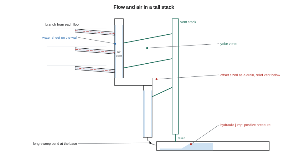
When water enters a vertical stack from a branch, it does not fall straight down the middle like a stone. It clings to the pipe wall and forms a ring or sheet that spirals down, with a core of air in the middle. The water accelerates as it falls, but friction with the pipe wall and the air soon balance gravity, and the water reaches a terminal velocity, typically around 10 to 15 ft/s, within the first several feet of fall. After that, it falls at roughly constant speed no matter how tall the building is. This is why a tall stack does not deliver water to the base at dangerous speeds, but it is also why the stack's capacity is limited: the annular sheet of water can only be so thick before it fills the pipe and blocks the air core.
Codes limit how full a stack may run, usually to between a quarter and a third of its cross-section, so that a clear air core remains. The tables that give the maximum drainage fixture units per stack size come from this limit. Exceed it, and the falling water starts to act like a piston, pushing air down ahead of it and pulling air in behind it, which creates pressure swings that can blow or siphon trap seals throughout the building.
Pressure in the stack and the threat to traps
Trap seals are only about 2 in of water. A pressure difference of about 2 in of water column, a tiny fraction of atmospheric pressure, is enough to push a seal out or pull it down the drain. In a tall stack carrying heavy flow, the falling water creates suction near the branches above and positive pressure near the base. Without venting, a toilet flushed on the tenth floor could siphon the traps of fixtures on nearby floors, and a slug of water arriving at the base could push sewer gas and foam out of the traps on the lowest floors.
Venting exists to keep these pressure swings small. In a tall building, that takes more than individual vents at each fixture. Designers add a separate vent stack beside each soil stack, connect the two at intervals, relieve pressure at offsets and at the stack base, and size everything for the air flow the falling water drags with it.
Branch intervals and stack sizing
Codes measure tall stacks in branch intervals. A branch interval is a section of stack, typically one story high and at least 8 ft, into which the horizontal branches from one floor connect. Stack sizing tables limit the total load on the stack and, separately, the load that can enter within any one branch interval. A stack of a given size can carry more fixture units in total than it can accept from a single floor, because water entering from several floors spreads out over time and space, while a large load entering at one level can momentarily fill the stack at that point.
Horizontal branches must also be sized not to overload the stack connection. A large branch entering a small stack, or two large branches entering opposite each other at the same level, can block the air core. Codes restrict opposing connections and the fittings used to connect branches, usually requiring sanitary tees or wyes that direct flow downward rather than straight across. Toilet connections near the base of a stack are often limited, because the positive pressure zone there can push water back up a short branch.
# Stack load check against a PRACTICE table (illustrative values, not the code table)
# stack size (in): (max DFU total, max DFU in one branch interval)
PRACTICE = {4: (240, 90), 5: (540, 200), 6: (960, 350), 8: (2200, 600)}

floors = {f"L{n}": dfu for n, dfu in zip(range(1, 9), [42, 64, 64, 64, 48, 48, 48, 30])}
total = sum(floors.values())
peak = max(floors.values())
print(f"stack S-2: total {total} DFU, largest branch interval {peak} DFU")
for size, (cap_total, cap_interval) in PRACTICE.items():
    ok = total <= cap_total and peak <= cap_interval
print(f" {size} in stack: total limit {cap_total:4d}, interval limit {cap_interval:3d} -> {'OK' if ok else 'too small'}")stack S-2: total 408 DFU, largest branch interval 64 DFU 4 in stack: total limit 240, interval limit 90 -> too small 5 in stack: total limit 540, interval limit 200 -> OK 6 in stack: total limit 960, interval limit 350 -> OK 8 in stack: total limit 2200, interval limit 600 -> OK
For stack S-2 at Ridgeview, which carries patient washrooms on eight floors, the practice table shows that a 4 in stack would be too small in total load and a 5 in stack is the smallest that works. The real design used the code table, which gave the same answer, and the engineer upsized the base of the stack and the building drain because of the offsets described next.
Vent stacks, yoke vents and relief vents
A vent stack is a vertical vent pipe that runs beside the soil or waste stack and connects to it at the bottom, below the lowest branch, and to the stack vent or to open air at the top. It provides an easy path for air to move into and out of the drainage system at every level. To make that path work along the whole height, codes require the vent stack and the soil stack to be cross-connected at intervals with yoke vents or relief vents, at intervals counted down from the top of the stack, every tenth branch interval under the International Plumbing Code on which Ohio's code is based. A yoke vent connects to the soil stack below the branches of one floor, rises at an angle, and joins the vent stack above the floor level, so it never carries water in normal use.
Relief vents are also required at offsets. When a stack shifts horizontally to clear a beam or a building setback, water falling down the upper part hits the horizontal section and slows abruptly, much as it does at the base of the stack. This creates positive pressure above the offset and the risk of trap seal loss on floors near it. Codes treat large offsets like a stack base and a new top: the horizontal offset is sized as a building drain, a relief vent is connected below the offset on the lower stack, and the upper section may need its own venting. Small offsets at a shallow angle may be exempt, but the rules differ between codes, so the installer follows the drawings and the code exactly.
The base of the stack
At the base of a tall stack, the falling water turns into the horizontal building drain. It cannot keep moving at terminal velocity along a pipe sloped at only 1/8 or 1/4 in per foot, so it slows, piles up and forms a hydraulic jump: a section of the drain where the flow suddenly becomes deeper and turbulent, sometimes filling the pipe. The jump creates a zone of positive pressure in the lower stack and the first part of the building drain. Designers reduce its effects by using long-radius or long-sweep bends at the base, by keeping branch connections away from the zone immediately downstream of the base, and by upsizing the building drain or adding a relief vent near the base so trapped air can escape.
Kitchens, laundries and other places where detergents are used create a special problem: suds. Foam generated as soapy water falls down a stack collects in the high-pressure zone at the base and can push up through the traps of the lowest fixtures. Codes in some jurisdictions require suds relief vents or prohibit lower-floor fixture connections in suds pressure zones near the base of stacks that carry detergent waste. On the Ridgeview drawings, the kitchen waste stack had a suds relief vent connected to the building drain just downstream of the base, and no fixtures were connected to the lowest several feet of the stack.
Pressure attenuators and single-stack systems
Two newer approaches reduce the size of the venting system. Air admittance valves let air into the drainage system when it is under suction but close to stop sewer gas escaping; codes allow them in some locations as a substitute for vent pipes, but never as the only vent for a whole building, and they cannot relieve positive pressure. Positive pressure attenuators are small chambers with a flexible bladder connected near the stack base that absorb the pressure pulses created by falling water. Together they are sometimes used to manage air pressure in tall stacks with fewer vent pipes, where the authority accepts them.
Single-stack drainage systems go further. Instead of a separate vent stack, they use special fittings at each floor, called aerators, that mix incoming branch water with the stack flow in a controlled way and keep the air core open, plus a de-aerator fitting at the base that separates air from the water before it enters the horizontal drain. These systems have been used in tall buildings for decades. They are engineered systems that must be designed and installed using the manufacturer's fittings and rules, and approved by the authority having jurisdiction. They show again that tall-building drainage is about controlling air as much as moving water.
Materials, supports and movement
Tall stacks are heavy, and they move. A cast iron stack full of water weighs hundreds of pounds per floor, so it is supported at every floor, usually with riser clamps resting on the floor slab, and at its base with a support that takes the stack's weight rather than letting it bear on the building drain fittings. Plastic stacks expand and contract with temperature much more than metal ones, roughly five times as much as cast iron. A tall plastic stack needs expansion joints or offsets that let it move, and its supports must allow that movement while keeping the pipe aligned. Building movement from settlement, wind sway and concrete shrinkage also affects tall stacks, which is why some designs include flexible joints where stacks pass from one structural zone to another.
Fire separations and noise also shape material choice. In many tall and noncombustible buildings, codes restrict combustible plastic drain pipe or require it to be enclosed in shafts with fire-resistance ratings and to be firestopped at every floor. Cast iron is quieter, which matters next to hospital bedrooms and hotel rooms. Ridgeview's specification called for no-hub cast iron for all soil and waste stacks above grade and for the patient washroom branches, with heavy-duty couplings on stacks taller than four floors.
Testing a tall drainage system
Drainage systems are tested before they are concealed, usually with water. Filling an entire tall stack with water would put extreme pressure on the lowest joints: a 100 ft column of water exerts about 43 psi at its base, far more than drainage joints are designed for. Codes therefore allow tall systems to be tested in sections, with the water head limited, commonly to about 10 ft above the highest joint in the section, using test plugs at each section boundary. Each section is filled, held for the required time and inspected, then drained before the next is tested. Air tests with low pressure are an alternative in some jurisdictions and for some materials, but plastic piping manufacturers often prohibit air testing because of the danger if a joint fails under compressed air.
Worked problem
Planning a sectional water test
Soil stack S-2 at Ridgeview rises 100 ft from the building drain to the roof. The specification limits the test head to 10 ft above the highest joint in each section, and the plumber wants to know the pressure at the bottom of one section and how many sections the stack needs if each section is one floor of 12.5 ft plus the 10 ft standpipe allowance.
Show solution
- Each section is tested with water standing 10 ft above its top joint, so the bottom joint sees one floor plus 10 ft of head.
- \[h = 12.5 + 10 = 22.5\ \text{ft}\]
- \[p = 0.433 \times 22.5 \approx 9.7\ \text{psi}\]
- \[n = \frac{100}{12.5} = 8\ \text{sections}\]
- If the whole stack were filled, the base would see about 43 psi, more than four times the sectional test pressure.
Answer: About 9.7 psi at the lowest joint of each section, with the stack tested in eight sections, one floor at a time.
After finishing, a final test of the completed system with fixtures connected may be required, using smoke or a low-pressure air test to confirm that trap seals hold and that there are no leaks into occupied spaces. In a hospital, the drainage system is also flushed and every trap is filled before patients move in, because dry traps let sewer gas and droplets into rooms.
Common mistakes
MistakeTreating a large stack offset like an ordinary bend.
InsteadLarge offsets need the horizontal section sized as a building drain and relief venting, as the code requires.
MistakeConnecting low-floor fixtures near the base of a detergent waste stack.
InsteadThe suds and positive pressure zone at the base can push foam and gas through traps.
MistakeTesting a tall stack with the full height filled with water.
InsteadTest in sections with the head limited so joints are not overloaded.
MistakeLetting a tall stack bear on the building drain fittings.
InsteadSupport the stack at each floor and at its base so its weight is carried by the structure.
Summary and key terms
- Water falls down stacks as an annular sheet around an air core and reaches terminal velocity within a few feet.
- Stacks are limited to running partly full so the air core remains; tables limit total load and load per branch interval.
- Vent stacks with yoke or relief vents at intervals, and relief at offsets, control pressure swings in tall stacks.
- A hydraulic jump at the stack base creates positive pressure; long sweeps, relief vents and connection limits manage it.
- Air admittance valves, pressure attenuators and single-stack systems are engineered alternatives where accepted.
- Tall stacks are supported at every floor, allowed to move, firestopped and tested in sections.
- Branch interval
- A section of stack, about one story high, into which the branches from one floor connect.
- Terminal velocity
- The steady speed falling water reaches when wall friction and air balance gravity.
- Yoke vent
- A vent connecting a soil stack to a vent stack at intervals to equalize pressure.
- Hydraulic jump
- A sudden deepening of flow where fast water from a stack slows in the horizontal drain.
- Suds pressure zone
- The section near a stack base where detergent foam can build up and push through traps.
Practice problems
Work each problem on paper first, then reveal the answer to check.
Why is a stack limited to running about a quarter to a third full?
Show answer
To keep an air core so the falling water does not act like a piston and disturb trap seals.
What is a branch interval?
Show answer
A section of stack, about one story and at least 8 ft, into which one floor's branches connect.
What pressure does a 65 ft column of water exert at its base?
Show answer
65 × 0.433 ≈ 28 psi.
Where does a yoke vent connect to the soil stack and to the vent stack?
Show answer
To the soil stack below the floor's branches, and to the vent stack above the floor level.
Why are long-sweep bends used at stack bases?
Show answer
They ease the change of direction and reduce the hydraulic jump and positive pressure.
Lesson quiz · 5 questions
Score 60% or more to complete this lesson.
Create a free account to save your progress, take quizzes and earn a certificate.