
PLB-330 · Lesson 6 of 12 · 20 min
Booster pumps, pressure zones and high-rise water supply
In PLB-130, Maya learned how Kingsway Tower's twelve stories were split into two pressure zones: the lower floors fed through a pressure-reducing valve station, and the upper floors fed directly by a triplex booster pump set. At Ridgeview, the same ideas came back with higher stakes. The new east wing is eight stories over a basement, but it connects to an existing hospital tower of eighteen stories, and the whole campus shares a central plant. The booster set serving the wing had to keep operating rooms, intensive care and dialysis supplied through a power failure, a pump failure and a city main shutdown. "At Kingsway, if the booster trips, residents complain," Raj said. "Here, if it trips, surgeons stop." This lesson goes deeper into booster pump selection, control and redundancy, and into pressure zoning for taller buildings.
Why tall buildings need zones
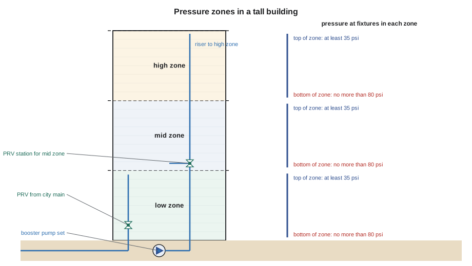
Water pressure changes with height: about 0.433 psi for every foot of elevation. A building 200 ft tall has nearly 87 psi less pressure at the top than at the bottom when the water is still. Plumbing fixtures work well within a fairly narrow range of pressure. Below about 20 to 30 psi, showers are weak and flush valves may not work properly; above 80 psi, the plumbing code requires a pressure-reducing valve, because high pressure wastes water, causes noise and splashing, and wears out valves and fixtures. Fitting an 87 psi difference into a band only about 50 psi wide is impossible with one system. The building has to be divided into vertical zones, each with its own pressure regime.
The usual target in each zone is a pressure at the top fixtures of at least the minimum the fixtures need, often around 35 psi for flush valves at the top of the zone, and no more than the code maximum at the lowest fixtures. With 35 psi at the top and 80 psi at the bottom, a zone can span about 45 psi, or roughly 104 ft of height. With stories about 12 ft tall, that is about eight or nine floors per zone.
Zoning arrangements
Designers use several arrangements to create zones, alone or in combination.
- City pressure for the low zone. The lowest floors are fed directly from the city main, often through a pressure-reducing valve if city pressure is high.
- Booster pumps with pressure-reducing valve stations. One booster set delivers enough pressure for the top zone, and each lower zone is fed through its own pressure-reducing valve station. This is common and keeps the pump plant in one place.
- Separate booster sets for each zone. Each zone gets its own pumps, sized for its height and flow. This avoids large pressure-reducing stations but needs more pumps and more floor space.
- Roof or intermediate tanks. Very tall buildings sometimes pump water up to storage tanks on intermediate mechanical floors or the roof, and let the zones below be fed by gravity. Tanks also provide reserve water during a supply interruption, but they must be designed and maintained so the water does not stagnate, and they add structural weight.
Pressure-reducing valve stations for zones are built with two valves in parallel, sized for low and high flow, so that small flows at night are controlled smoothly and peak flows are still met. Each station has isolation valves, a bypass arrangement or redundant valves so one can be serviced without shutting off the zone, strainers, gauges on both sides, and a pressure relief valve on the low-pressure side in case a valve fails open. Kingsway's station used 2 in and 3 in valves in parallel; larger buildings may use three.
Booster pump sets
A modern domestic water booster set is a packaged assembly of two or more pumps on a common base with suction and discharge headers, check and isolation valves on each pump, a pressure sensor on the discharge, a control panel and usually variable-frequency drives. The drives speed the pumps up and down to hold a constant discharge pressure as demand changes. At low flow, one pump runs slowly; as demand rises, it speeds up, and a second pump starts when the first reaches its limit. Pumps alternate duty so they wear evenly. A small hydropneumatic tank on the discharge stores a little pressurized water so the pumps do not start and stop for every small draw, such as a single toilet refilling at night.
Booster sets connected directly to the city main must protect the main. If the pumps pulled too hard on the suction side, they could drop the pressure in the city main and affect neighbors or, in the worst case, create a vacuum. Utilities therefore require a low suction pressure cutoff that stops the pumps if suction pressure falls below a set value, and many limit the maximum flow a booster may draw. A backflow preventer at the service, required anyway for a building of this kind, protects the main from water returning from the building. Some utilities require a break tank, an open tank with an air gap fill, between the main and the pumps, which fully isolates the building but brings tank maintenance and water quality duties.
Calculating the pump head
The booster must lift water from the pump to the highest fixture it serves, overcome friction in the pipe and fittings, and still deliver the minimum pressure the highest fixture needs. The city main helps by supplying some pressure at the pump suction. The pump only has to make up the difference. Designers use the minimum suction pressure the utility guarantees, because the pump must work even when the main is at its weakest.
Worked problem
Boost for the Ridgeview wing's upper zone
The east wing's upper zone serves floors 5 to 8. The highest fixture is 108 ft above the booster. Friction loss through the riser, fittings, meter and backflow preventer at peak flow is estimated at 12 psi. Flush valves at the top need 35 psi. The utility guarantees a minimum of 43 psi at the pump suction. What pressure boost must the pumps provide?
Show solution
- Static lift: 108 × 0.433 ≈ 47 psi.
- Total required at the pump discharge: 47 + 12 + 35 = 94 psi.
- Boost: 94 − 43 = 51 psi (about 118 ft of head).
Answer: About 51 psi of boost at the design flow. The pump curve is checked at that flow, and the zone below is fed through a pressure-reducing station.
# Booster head and power estimate (practice values)
PSI_PER_FT = 0.433

def boost_psi(lift_ft, friction_psi, residual_psi, min_suction_psi):
    return lift_ft * PSI_PER_FT + friction_psi + residual_psi - min_suction_psi

def power_hp(flow_gpm, head_psi, efficiency=0.65):
    head_ft = head_psi / PSI_PER_FT
    return flow_gpm * head_ft / (3960 * efficiency)

b = boost_psi(108, 12, 35, 43)
print(f"boost required: {b:.0f} psi = {b / PSI_PER_FT:.0f} ft of head")
for q in (50, 100, 150):
print(f"at {q} gpm: brake horsepower about {power_hp(q, b):.1f} hp")boost required: 51 psi = 117 ft of head at 50 gpm: brake horsepower about 2.3 hp at 100 gpm: brake horsepower about 4.6 hp at 150 gpm: brake horsepower about 6.8 hp
Pump curves and the operating point
A pump does not deliver a fixed pressure. Its curve shows that as flow increases, the pressure it can add falls. The building's system curve shows the opposite: the pressure needed rises with flow, because friction increases roughly with the square of the flow, on top of the fixed static lift and residual pressure. Where the two curves cross is the operating point. With variable-speed pumps, the controller shifts the pump curve up or down by changing speed so that the operating point stays at the set discharge pressure across a wide range of flows.
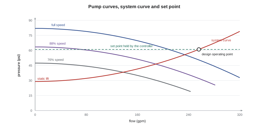
Selecting the pump means choosing a model whose curve meets the design point near its best efficiency, with enough margin for the future but not so much that it runs inefficiently or causes high pressure at low flow. Selecting several smaller pumps rather than one large one gives redundancy and better efficiency at the low flows that occur most of the time.
Redundancy and resilience in health care
Health care buildings add requirements that an apartment tower may not have. The booster set must have at least one standby pump, so that with any one pump out of service the remaining pumps still meet peak demand. It must be on standby power, so that a utility outage does not stop the water. Controls must fail safely: if the pressure sensor or drive fails, a bypass or a fixed-speed mode keeps water flowing. Many hospitals have two water services from different mains, with backflow preventers on each, so that a main break or utility shutdown on one street does not cut the supply. Some keep emergency water storage on site for a set number of hours.
At Ridgeview, the booster set had three pumps, each able to carry half of the peak flow, giving full capacity with one pump out of service. Each pump had its own drive, so a drive failure took out only one pump. The set was connected to the essential electrical system, and the controller sent alarms to the building automation system for low suction pressure, high discharge pressure, pump failure and drive failure. Two parallel reduced pressure principle assemblies on each water service let one be tested or repaired while the other kept water flowing.
Installation and commissioning
Booster sets are heavy, vibrating machines. They sit on a housekeeping pad with vibration isolation, and their suction and discharge connections use flexible connectors so pump vibration does not travel through the piping into the structure. Suction piping is sized generously and laid out with straight runs into the header, because turbulence at the pump inlet reduces performance and causes noise. Isolation valves on every pump allow service without shutting down the set. Pressure gauges or transducers on suction and discharge, a drain, and a test connection for flow are included. The relief and drain discharges are piped to a floor drain with an air gap.
Commissioning a booster set involves more than turning it on. The installer flushes and disinfects the piping, fills and vents the system, checks pump rotation, and then works with the manufacturer's technician to set the discharge pressure, the low suction cutoff, the staging and the alternation. The pressure-reducing stations are set and checked at low and high flow. Each failure mode is tested: a pump is switched off to confirm the standby starts, power is cut to confirm the transfer to standby power, and the low suction cutoff is checked. The results go into the commissioning record. Lesson 12 returns to commissioning on large projects.
Start-up and testing of booster systems
A booster pump set is started up with the manufacturer's representative, following a checklist. Before starting, the installer confirms that the suction and discharge piping are flushed and supported independently of the pumps, the isolation valves and check valves are installed in the right direction, the pressure sensors are connected, the pumps are filled and vented, and the electrical supply matches the motor nameplates. The representative then programs the controller with the set pressure, the start and stop points for each pump, the low suction cutout and the alarms.
Tests prove that the system does what the design requires. Each pump is run alone and its pressure and flow are checked against its curve. The lead pump is shut off to show that the lag pump starts. Suction pressure is lowered to show that the low suction cutout protects the pumps and the city main. A power failure is simulated to prove that the set restarts on standby power. The results go into the commissioning record, and the owner's staff are trained on how to read the controller and what each alarm means.
Common mistakes
MistakeSizing booster pumps from the normal city pressure.
InsteadUse the minimum suction pressure the utility guarantees, so the pumps work when the main is weakest.
MistakeOmitting the low suction pressure cutoff.
InsteadUtilities require it so the booster cannot pull the city main into low or negative pressure.
MistakeBuilding a zone pressure station with a single valve and no bypass.
InsteadUse parallel valves, isolation and relief so service does not shut down the zone.
MistakeHard-piping a booster set to the risers.
InsteadUse flexible connectors and isolation to stop vibration traveling into the building.
Summary and key terms
- Pressure falls about 0.433 psi per foot of height, so tall buildings are divided into zones.
- Each zone keeps its fixtures between a minimum, often around 35 psi at the top, and the code maximum of 80 psi at the bottom.
- Zones are created with city pressure, pressure-reducing stations, separate booster sets or tanks.
- Variable-speed booster sets hold a constant discharge pressure; utilities require low suction cutoffs.
- Pump boost equals lift plus friction plus top residual minus minimum suction pressure.
- Health care boosters need standby pumps, standby power, fail-safe controls and often redundant services.
- Pressure zone
- A vertical section of a building served at its own pressure range.
- Booster pump set
- A packaged group of pumps that raises water pressure for upper floors.
- Low suction pressure cutoff
- A control that stops a booster if the pressure at its inlet falls too low.
- Hydropneumatic tank
- A small pressurized tank that stores water so pumps do not cycle for small draws.
- Operating point
- The flow and pressure where a pump curve crosses the system curve.
Practice problems
Work each problem on paper first, then reveal the answer to check.
A zone spans from 35 psi at the top to 80 psi at the bottom. About how tall can it be?
Show answer
45 psi ÷ 0.433 ≈ 104 ft.
Lift 80 ft, friction 10 psi, residual 35 psi, minimum suction 40 psi. What boost is needed?
Show answer
80 × 0.433 ≈ 35; 35 + 10 + 35 − 40 = 40 psi.
Why do health care booster sets have a standby pump?
Show answer
So peak demand is still met with any one pump out of service.
What does a hydropneumatic tank prevent?
Show answer
Pumps starting and stopping for every small draw.
Why are two pressure-reducing valves installed in parallel at a zone station?
Show answer
A small valve controls low flows smoothly and a large one meets peak flow; redundancy allows service.
Lesson quiz · 5 questions
Score 60% or more to complete this lesson.
Create a free account to save your progress, take quizzes and earn a certificate.