
NET-110 · Lesson 2 of 12 · 30 min
The OSI and TCP/IP models
▶ Video coming soon A video version of this lesson is on the way.
When Sam phones the provider about a slow connection, the support agent asks a string of questions: is the light on the optical terminal green, can the firewall reach the provider's gateway, do web pages load by address but not by name? Jordan, listening on speakerphone, notices that the agent is working through the problem in a definite order, from the physical line upward. That order comes from a layered model of networking, a way of splitting the enormous job of moving data into separate layers, each with its own responsibilities and protocols.
This lesson introduces the two models every networking professional uses: the seven-layer OSI reference model, which gives everyone a shared vocabulary, and the four-layer TCP/IP model, which describes how the internet's protocols are actually organized. It explains encapsulation, the process by which each layer wraps the data of the layer above, and shows how the models turn troubleshooting into an orderly search instead of guesswork.
Why networking is split into layers
Moving a till's sale record from the cafe counter to a payment service hundreds of kilometers away involves many separate problems. Bits must be turned into electrical signals or light pulses and back. Devices on the same cable must take turns and detect errors. Data must be addressed and routed across dozens of networks. Lost pieces must be noticed and sent again. Both programs must agree on the format of the messages they exchange. Solving all of that in one huge program would be impossible to build and impossible to change.
Layering divides the work. Each layer solves one set of problems, offers a service to the layer above and relies on the service of the layer below, without needing to know how the other layers do their jobs. A web browser does not care whether the connection runs over Wi-Fi, copper or fiber; a switch does not care whether the data inside a frame is an email or a video. This independence is what lets Ridgeline replace its access points without touching the tills' software, and lets a new application work over every kind of network on day one.
Layering also gives people a common language. When a technician says a problem is at layer 1, everyone knows to look at cables, ports and signals; layer 3 means addressing and routing; layer 7 means the application itself. Exams, documentation and equipment specifications all use these numbers, so it is worth learning them well.
The OSI reference model
The Open Systems Interconnection model was published by the International Organization for Standardization in the early 1980s. The protocol suite designed alongside it never caught on, but its seven-layer model became the standard way to talk about networks. Layers are numbered from the bottom, starting with the physical cable.
| Layer | Name | Responsibility | Unit of data | Examples |
|---|---|---|---|---|
| 7 | Application | Network services used directly by applications | Data | HTTP, DNS, SMTP, SSH |
| 6 | Presentation | Formats, character encoding, compression and encryption | Data | TLS (in part), JPEG, UTF-8 |
| 5 | Session | Setting up, managing and ending conversations | Data | Session handling in RPC, NetBIOS |
| 4 | Transport | End-to-end delivery between programs; reliability and ports | Segment (TCP) or datagram (UDP) | TCP, UDP |
| 3 | Network | Logical addressing and routing between networks | Packet | IPv4, IPv6, ICMP |
| 2 | Data link | Delivery on one local link; hardware addresses; error detection | Frame | Ethernet, Wi-Fi (802.11), ARP |
| 1 | Physical | Bits as signals on a medium; connectors, cables and radio | Bit | Copper twisted pair, fiber, radio |
Several memory aids exist for the order. From the bottom up, Please Do Not Throw Sausage Pizza Away gives Physical, Data link, Network, Transport, Session, Presentation, Application. From the top down, All People Seem To Need Data Processing does the same in reverse. Any phrase that works for you is fine; what matters is being able to place a protocol, device or symptom at the right layer quickly.
Devices are often described by the highest layer they work at. A hub or a cable is a layer 1 device: it simply repeats signals. A switch is a layer 2 device, forwarding frames by MAC address. A router is a layer 3 device, forwarding packets by IP address. Firewalls and load balancers can work at layers 3 and 4, looking at addresses and ports, or up to layer 7, looking at the content of web requests. You will also hear of layer 3 switches, which combine switching with routing in one box.
The upper three layers of OSI are often blurred together in practice. In the internet's protocols, sessions, formats and encryption are usually handled inside the application or by a library such as TLS that sits just above the transport layer. That is one reason the TCP/IP model, below, has only one application layer covering all three.
Try it yourself
Name the OSI layer
Write osi_name(n) that returns the name of OSI layer n (1 to 7) as a string: Physical, Data link, Network, Transport, Session, Presentation or Application. For any other number, return None.
Then write osi_number(name) that does the reverse, ignoring capital letters, and returns None for an unknown name.
LAYERS = ['Physical', 'Data link', 'Network', 'Transport', 'Session', 'Presentation', 'Application']

def osi_name(n):
    return LAYERS[n]

def osi_number(name):
    return LAYERS.index(name)

print(osi_name(3), osi_number('transport'))
The TCP/IP model
The protocols that run the internet were designed in the 1970s, before OSI, by researchers working on the ARPANET and its successors. Their model has four layers, and it describes the real protocol suite rather than an ideal one. Some textbooks split its bottom layer in two and show five layers; the ideas are the same.
| TCP/IP layer | Matching OSI layers | Job | Main protocols |
|---|---|---|---|
| Application | 5, 6 and 7 | Services for programs, including formats and encryption | HTTP, HTTPS, DNS, DHCP, SMTP, SSH, NTP |
| Transport | 4 | Delivery between programs on two hosts, using port numbers | TCP, UDP |
| Internet | 3 | Addressing and routing packets across networks | IPv4, IPv6, ICMP |
| Link (network access) | 1 and 2 | Delivery on one physical network | Ethernet, Wi-Fi, ARP |
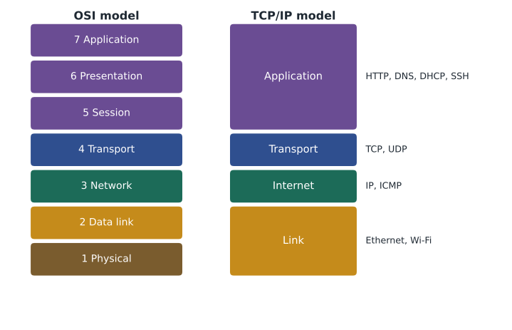
The narrow waist of the TCP/IP model is the Internet layer. Many applications sit above it and many kinds of link sit below it, but almost everything in between passes through one protocol, IP. That single common layer is what lets a phone on cafe Wi-Fi exchange data with a server on a data center fiber link: each network only has to carry IP packets, and each application only has to hand its data to TCP or UDP.
People switch between the two models freely. They describe protocols with the TCP/IP model, because that is how the protocols are grouped, but they number layers with OSI, because the numbers are a shared shorthand. So you will hear that IP is the Internet layer protocol and also that routers are layer 3 devices. Both statements describe the same thing.
Encapsulation: how the layers wrap data
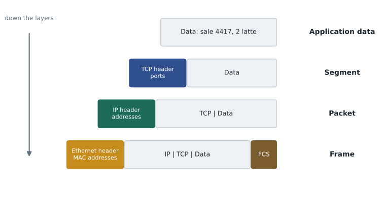
When a program sends data, each layer adds its own header in front, carrying the information that layer needs, and passes the result down. This wrapping is called encapsulation. The till's sale record becomes the payload of an application message; the transport layer adds a TCP header with port numbers and sequence numbers, making a segment; the Internet layer adds an IP header with source and destination addresses, making a packet; and the link layer adds an Ethernet header with MAC addresses and a trailer with an error-checking code, making a frame, which the physical layer sends as bits.
At the receiving end the process runs in reverse, called de-encapsulation. The network card checks the frame's trailer for errors and strips the Ethernet header; the IP layer checks the destination address and strips the IP header; TCP uses the port number to hand the data to the right program, in the right order. Each layer reads only its own header, which is exactly the independence that layering promised.
Routers strip and rebuild only the link layer as a packet travels. A packet from the cafe to the payment service crosses perhaps fifteen routers, and each one removes the incoming frame, reads the IP header to choose the next hop, and wraps the packet in a new frame for the next link, with new MAC addresses. The IP addresses inside stay the same from end to end, apart from the address translation done at the edge of most small networks, which Lesson 7 explains.
def encapsulate(data):
    segment = {'src_port': 51432, 'dst_port': 443, 'payload': data}
    packet = {'src_ip': '192.168.1.21', 'dst_ip': '203.0.113.80', 'payload': segment}
    frame = {'src_mac': '3c:22:fb:10:00:21', 'dst_mac': '00:1b:2c:aa:00:01', 'payload': packet, 'fcs': 'ok'}
    return frame

def show(unit, depth=0):
    for key, value in unit.items():
        if isinstance(value, dict):
            print('  ' * depth + key + ':')
            show(value, depth + 1)
        else:
            print('  ' * depth + key + ' = ' + str(value))

show(encapsulate('sale 4417: 2 latte, 10.50'))src_mac = 3c:22:fb:10:00:21
dst_mac = 00:1b:2c:aa:00:01
payload:
src_ip = 192.168.1.21
dst_ip = 203.0.113.80
payload:
src_port = 51432
dst_port = 443
payload = sale 4417: 2 latte, 10.50
fcs = okEach header costs bytes. A full Ethernet frame carries at most 1,500 bytes of IP packet, called the maximum transmission unit or MTU, and the Ethernet header and trailer add 18 more. An IPv4 header without options is 20 bytes and a basic TCP header is another 20, leaving 1,460 bytes for the application's data. Those numbers come up again in Lesson 8 and whenever someone has to explain why a tunnel or a VPN makes some websites misbehave: extra headers shrink the room left for data.
Try it yourself
Unwrap a frame
A received frame is modeled as nested dictionaries: the frame has a payload that is the packet, the packet has a payload that is the segment, and the segment has a payload that is the application data, a string.
Write unwrap(frame) that returns a tuple (data, dst_ip, dst_port): the application data, the destination IP address from the packet and the destination port from the segment. The variable FRAME is already defined for you to try.
def unwrap(frame):
    return frame['payload'], frame['dst_mac'], None

print(unwrap(FRAME))
Troubleshooting with the layers
The layers give troubleshooting a structure. One common approach, bottom-up, starts at layer 1 and works up: is the cable plugged in and the link light on; does the device have a valid hardware connection to the switch or access point; does it have a correct IP address, mask and gateway, and can it reach the gateway; can it reach a remote address; does name resolution work; does the application itself respond? Each step that passes rules out the layers below it. Top-down starts at the application and works down, which is quicker when lower layers are clearly working, for example when every other website loads and only one fails. Divide and conquer starts in the middle, usually by pinging a remote address, and moves up or down depending on the result.
| Symptom | Likely layer | First checks |
|---|---|---|
| No link light on the port | 1 Physical | Cable seated, cable tested, port enabled, device powered |
| Wi-Fi connects to the wrong network or keeps dropping | 1 or 2 | Signal strength, channel interference, saved network settings |
| Device has an address starting 169.254 | 3 Network (DHCP failed) | DHCP server reachable, correct network segment |
| Can reach local devices but not the internet | 3 Network | Default gateway setting, router uplink, provider status |
| Websites load by IP address but not by name | 7 Application (DNS) | DNS server settings, resolver reachability |
| One application fails while others work | 4 or 7 | Firewall rules for its port, service status on the server |
Writing down the layer you are checking keeps a troubleshooting session honest. It stops people jumping from cable to application and back, re-testing things that already passed, and it produces notes that someone else can follow if the problem returns. The Saturday outage at Ridgeline fitted the table exactly: tills could print receipts and reach the office printer, layers 1 to 3 on the LAN were fine, but nothing beyond the firewall answered, which pointed straight at the provider.
Try it yourself
Where should troubleshooting start?
Write first_layer(symptom) that returns the OSI layer number to check first for a symptom string, using these rules in order: if the text contains cable or link light, return 1; if it contains 169.254, return 3; if it contains gateway or internet, return 3; if it contains by name or dns, return 7; otherwise return 7. Ignore capital letters.
def first_layer(symptom):
    if 'cable' in symptom:
        return 1
    return 7

print(first_layer('No link light on port 7'))
Worked problem
Placing a problem on the model
Mei reports that the cafe tablet shows the guest Wi-Fi as connected, has the address 192.168.50.57, and can open a web page by typing its IP address, but cannot open any site by name. Which layers are working and where should Sam look?
Show solution
- Layers 1 and 2: the tablet is associated with the access point and has a link, so the radio and Wi-Fi layers work.
- Layer 3: it has a valid address in the guest network and reaches a remote IP address, so addressing and routing work.
- Layer 4: opening a page by address uses TCP successfully, so the transport layer works.
- Layer 7: names fail while addresses work, so name resolution is the problem: the DNS server handed out to guest devices is wrong or unreachable.
- Check the DNS settings in the guest network's DHCP configuration on the firewall-router.
Answer: Layers 1 to 4 are working; the fault is DNS at the application layer, most likely the DNS server address given to guest devices.
Common mistakes
MistakeLearning the layer names without the job each layer does.
InsteadTie each layer to its responsibility, its unit of data and a protocol example.
MistakeNumbering OSI layers from the top.
InsteadLayer 1 is Physical at the bottom; layer 7 is Application at the top.
MistakeThinking routers change the IP addresses of every packet.
InsteadRouters rebuild the frame for each link; IP addresses stay the same end to end apart from address translation at the edge.
MistakePlacing DNS or DHCP at the network layer because they deal with addresses.
InsteadThey are application layer protocols that happen to help with addressing.
MistakeJumping between layers at random while troubleshooting.
InsteadWork bottom-up, top-down or from the middle, and record what has been ruled out.
MistakeForgetting that headers use up part of every frame.
InsteadAllow for header overhead when estimating throughput and when tunnels shrink the MTU.
Summary and key terms
- Layered models split networking into independent jobs, each offering a service to the layer above.
- OSI has seven layers: Physical, Data link, Network, Transport, Session, Presentation and Application.
- The TCP/IP model has four: Link, Internet, Transport and Application, and describes the real protocol suite.
- Units of data are bits, frames, packets, segments or datagrams, and data, from the bottom up.
- Encapsulation adds a header at each layer on the way down; de-encapsulation removes them on the way up.
- Switches work at layer 2 with MAC addresses; routers work at layer 3 with IP addresses.
- Layered troubleshooting checks one layer at a time, bottom-up, top-down or from the middle.
- OSI model
- A seven-layer reference model used as a shared vocabulary for networking.
- TCP/IP model
- The four-layer model that describes how the internet's protocols are organized.
- Encapsulation
- Adding a layer's header (and sometimes trailer) around the data from the layer above.
- Frame
- The unit of data at the data link layer, carrying MAC addresses.
- Packet
- The unit of data at the network layer, carrying IP addresses.
- Segment
- The unit of data for TCP at the transport layer.
- Datagram
- The unit of data for UDP, and for IP in some texts.
- MTU
- Maximum transmission unit: the largest packet a link carries in one frame, 1,500 bytes on standard Ethernet.
- Payload
- The data carried inside a header at any layer.
Practice problems
Work each problem on paper first, then reveal the answer to check.
At which OSI layer do IP addresses work?
Show answer
Layer 3, Network.
Which OSI layers does the TCP/IP Application layer cover?
Show answer
Layers 5, 6 and 7.
What is the unit of data at layer 2?
Show answer
A frame.
Which header does a router remove and rebuild at every hop?
Show answer
The link layer (Ethernet) header and trailer.
Put these in order from the top: packet, data, frame, segment.
Show answer
Data, segment, packet, frame.
A device has no link light. Which layer do you check first?
Show answer
Layer 1, Physical.
At which layer does a switch normally work?
Show answer
Layer 2, Data link.
How many bytes of application data fit in a standard Ethernet frame carrying TCP over IPv4 with no options?
Show answer
1,500 - 20 - 20 = 1,460 bytes.
Is DNS a network layer protocol?
Show answer
No, it is an application layer protocol.
What does the trailer added at the data link layer do?
Show answer
It carries an error-detection code (the frame check sequence) so the receiver can discard damaged frames.
Lesson quiz · 5 questions
Score 60% or more to complete this lesson.
Create a free account to save your progress, take quizzes and earn a certificate.