
LVT-110 · Lesson 4 of 12 · 18 min
Series and parallel circuits and voltage drop
Few low-voltage circuits are a single supply feeding a single load. A power supply feeds several locks; a door has a contact, a request-to-exit sensor and a lock in one controller loop; a chain of speakers hangs on one paging line; a camera sits at the end of a long run of cable that has its own resistance. This lesson extends Ohm's law to circuits with several components, in series, in parallel and in combination, and then applies the results to the calculation every installer must be able to make: how much voltage is lost along a cable run, and whether the device at the far end will work.
Series circuits
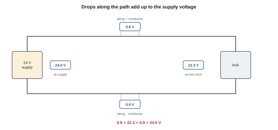
In a series circuit the components are connected end to end, so there is only one path for the current. The same current flows through every component, and the supply voltage is shared among them. The total resistance is the sum of the individual resistances, and the voltages across the components add up to the supply voltage. That last rule, Kirchhoff's voltage law, is the basis of most voltage-drop troubleshooting.
Every circuit that runs from a supply through a cable to a load is a series circuit: the supply, the outgoing conductor, the load and the returning conductor are in series. The cable's conductors are resistances, small ones, but resistances that take their share of the voltage. Door contact loops in alarm systems are series circuits too: several normally closed contacts in a row, so that opening any one breaks the loop. Many alarm and access control inputs add end-of-line resistors to such loops, so the panel can tell a normal closed loop from a cut wire or a short. Lesson 9 shows how a meter reads those resistors.
In a series circuit, a break anywhere stops the current everywhere. That is useful in an alarm loop and a nuisance in a string of decorative lights. It also means that a fault can be found by measuring voltage across each component in turn: a closed contact or a healthy conductor shows almost no voltage, and an open contact shows the full supply voltage across it.
Parallel circuits
In a parallel circuit the components are connected across the same two points, so each has the full supply voltage and its own path for current. The total current is the sum of the branch currents, a rule called Kirchhoff's current law, and the total resistance is less than the smallest branch resistance. For two branches the total resistance is their product divided by their sum; for any number, the reciprocal of the total is the sum of the reciprocals.
Most power distribution in low-voltage systems is parallel. A power supply output feeding four locks feeds them in parallel: each lock sees the supply voltage, each draws its own current, and the supply delivers the total. Removing one lock leaves the others working. Speakers on a 70 V paging line are also connected in parallel across the line, each with its own transformer tapped at a chosen power, so that the amplifier's load is the sum of the taps.
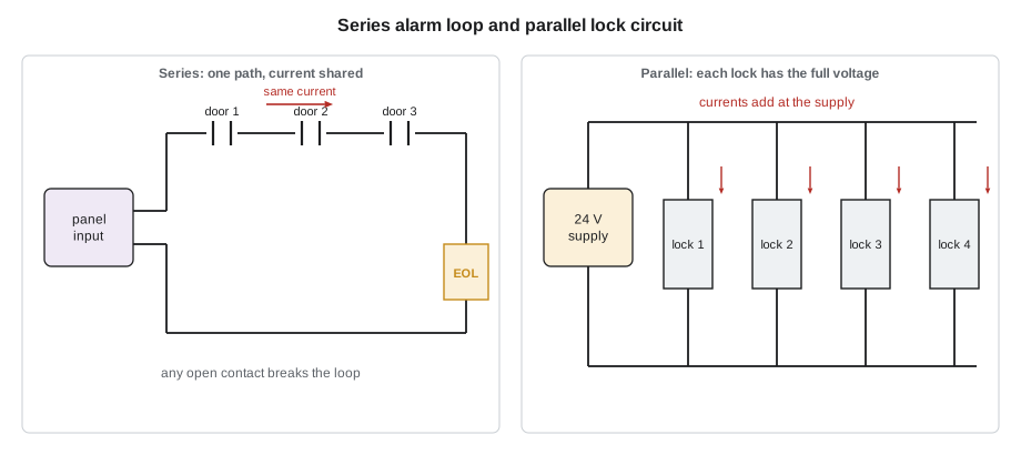
Real circuits combine both. Four locks connected in parallel at the end of one shared cable form a series-parallel circuit: the cable is in series with the group, and the group is in parallel. Such circuits are solved in steps, by reducing each parallel group to its equivalent resistance or total current and then treating the result as part of the series path.
Voltage drop on a cable run
Every cable has resistance, so every load at the end of a cable receives less than the supply voltage. The difference is the voltage drop. For a two-conductor DC circuit, the current flows out on one conductor and back on the other, so the loop resistance is twice the resistance of one conductor over the run length. The voltage drop is the current multiplied by that loop resistance.
Here L is the one-way length of the run and r is the resistance of one conductor per unit length, from a table such as the one in Lesson 3. Manufacturers of locks, cameras and readers give an operating voltage range, often plus or minus ten or fifteen percent of the nominal voltage, and the drop must leave the device inside that range under its highest current. For a 12 V camera the allowance is small, about 1.2 V; for a 24 V lock it is about 2.4 V; which is one reason 24 V systems are preferred for long runs.
# Voltage drop on a two-conductor DC run, and the smallest wire that works
R_PER = {"22 AWG": 16.1, "18 AWG": 6.4, "16 AWG": 4.0, "14 AWG": 2.5}  # ohm per 1000 ft per conductor
def drop(i, length, gauge):
    return i * 2 * length * R_PER[gauge] / 1000
runs = [("camera, 12 V, 0.55 A", 12.0, 0.55, 250), ("maglock, 24 V, 0.50 A", 24.0, 0.50, 400),
        ("strike, 24 V, 0.45 A", 24.0, 0.45, 200)]
for name, v, i, length in runs:
    print(f"{name}, run {length} ft:")
    for g in R_PER:
        vd = drop(i, length, g)
        ok = "ok" if vd <= 0.10 * v else "too much"
print(f" {g}: drop {vd:4.2f} V ({100 * vd / v:4.1f} %), {v - vd:5.2f} V at device {ok}")camera, 12 V, 0.55 A, run 250 ft: 22 AWG: drop 4.43 V (36.9 %), 7.57 V at device too much 18 AWG: drop 1.76 V (14.7 %), 10.24 V at device too much 16 AWG: drop 1.10 V ( 9.2 %), 10.90 V at device ok 14 AWG: drop 0.69 V ( 5.7 %), 11.31 V at device ok maglock, 24 V, 0.50 A, run 400 ft: 22 AWG: drop 6.44 V (26.8 %), 17.56 V at device too much 18 AWG: drop 2.56 V (10.7 %), 21.44 V at device too much 16 AWG: drop 1.60 V ( 6.7 %), 22.40 V at device ok 14 AWG: drop 1.00 V ( 4.2 %), 23.00 V at device ok strike, 24 V, 0.45 A, run 200 ft: 22 AWG: drop 2.90 V (12.1 %), 21.10 V at device too much 18 AWG: drop 1.15 V ( 4.8 %), 22.85 V at device ok 16 AWG: drop 0.72 V ( 3.0 %), 23.28 V at device ok 14 AWG: drop 0.45 V ( 1.9 %), 23.55 V at device ok
The camera run shows how quickly 12 V circuits run out of margin: at 250 ft, 16 AWG is the smallest size that keeps the drop within ten percent, and at about nine percent it leaves almost no margin, so many installers would use 14 AWG, move the camera's power supply closer or use PoE. The 24 V lock at 400 ft works on 16 AWG or larger. The strike at 200 ft works on 18 AWG.
Two corrections make the simple calculation more realistic. First, the conductor resistance in a warm ceiling may be eight to ten percent higher than the table's figure at 68 °F. Second, a constant-power load draws more current as its voltage falls, so the drop is a little larger than the calculation using the nominal current. Sanjay's design spreadsheet adds a margin for both; in the field, the simplest check is to measure the voltage at the device while it is drawing its highest current, such as when a lock is energized or a camera's infrared illuminators are on at night.
Several loads on one cable
When several devices hang on one cable, such as three cameras fed from one supply along a corridor, the current in each section of the cable is the sum of the currents of the devices beyond it. The first section, nearest the supply, carries all three cameras' current and has the greatest drop per meter; the last carries only one. The voltage at each device is the supply voltage minus the sum of the drops of all the sections before it. Daisy-chaining power this way saves cable but makes the farthest device the weakest, and Sanjay's designs usually run a separate pair to each device from the supply, a home run, which also makes faults easier to isolate.
# Three cameras daisy-chained on one 18 AWG pair (one-way section lengths)
r = 6.4 / 1000        # ohm per ft per conductor
v = 24.0
sections = [(130, 0.40), (100, 0.40), (100, 0.40)]   # length, camera current at the end of each section
load_after = [sum(c for _, c in sections[k:]) for k in range(len(sections))]
for k, ((length, _), i) in enumerate(zip(sections, load_after), 1):
    vd = i * 2 * length * r
    v -= vd
print(f"section {k}: carries {i:.2f} A, drop {vd:.2f} V, camera {k} sees {v:.2f} V")section 1: carries 1.20 A, drop 2.00 V, camera 1 sees 22.00 V section 2: carries 0.80 A, drop 1.02 V, camera 2 sees 20.98 V section 3: carries 0.40 A, drop 0.51 V, camera 3 sees 20.47 V
Voltage drop and troubleshooting
Voltage drop is also the most useful troubleshooting tool in the trade. When a device misbehaves, Maya measures the voltage at the supply and at the device, both while the device is drawing current. If the difference is larger than the calculation predicts, the extra resistance is somewhere in the path: a corroded splice, a loose terminal, a wire nut that caught only one conductor, a punch-down that cut a strand. She can then measure the voltage across each part of the path, conductor by conductor and connection by connection, and the part with the abnormal drop is the fault. A good connection shows a few millivolts; a bad one shows tenths of a volt or more.
Measuring with no load connected hides these faults. An open circuit has no current, so there is no drop in the cable, and the meter reads the full supply voltage at the device terminals even through a poor splice. That is why Dev insists on measuring under load.
Worked problem
Sizing the cable for a lobby maglock pair
At Juniper Point, two 24 V DC maglocks on the lobby double doors draw 0.5 A each and are fed together from a supply 280 ft away in the telecommunications room. The lock manufacturer allows 21.6 V minimum. Which wire size is needed?
Show solution
- The locks are in parallel, so the cable carries 0.5 + 0.5 = 1.0 A.
- Allowable drop: 24.0 − 21.6 = 2.4 V. Allowable loop resistance: 2.4 / 1.0 = 2.4 Ω.
- Loop length is 2 × 280 = 560 ft. Allowable resistance per 1,000 ft: 2.4 / 0.560 = 4.3 Ω per 1,000 ft.
- 16 AWG at about 4.0 Ω per 1,000 ft just meets it; adding a warm-ceiling margin of ten percent makes it 4.4, slightly over. Sanjay specifies 14 AWG, at 2.5 Ω per 1,000 ft, which gives a drop of about 1.4 V.
Answer: 14 AWG, because 16 AWG leaves no margin for temperature and the constant-power behavior of the locks' electronics.
One more practical point about end-of-line resistors: they must be installed at the far end of the loop, at the last device, not at the panel. A resistor fitted at the panel terminals makes the panel see a healthy loop even when the cable beyond it is cut, which defeats the supervision the resistor exists to provide. Maya checks resistor location on every alarm and access control input she wires.
Common mistakes
MistakeUsing the one-way length in the voltage-drop formula.
InsteadUse twice the length, because current flows out and back.
MistakeMeasuring device voltage with the device switched off.
InsteadMeasure under load, when the device draws its highest current.
MistakeSizing a shared feeder for one device's current.
InsteadAdd the currents of all the devices it feeds.
MistakeDaisy-chaining power to many devices without checking the last one.
InsteadCalculate the cumulative drop, or use home runs.
MistakeAssuming the table resistance applies in a hot ceiling.
InsteadAdd a margin for temperature.
Summary and key terms
- In series, the same current flows through every part and the voltages add to the supply voltage.
- In parallel, every branch has the full voltage and the currents add; total resistance is less than the smallest branch.
- Voltage drop on a two-wire DC run is I × 2L × r; the device must stay inside its operating range at its highest current.
- In daisy chains, each section carries the current of every device beyond it.
- Voltage drop measured section by section, under load, finds bad splices and terminals.
- Series circuit
- A circuit with one current path through all its components.
- Parallel circuit
- A circuit in which components connect across the same two points, each with its own path.
- Kirchhoff's voltage law
- Around any closed loop, the voltage drops add up to the source voltage.
- Kirchhoff's current law
- The currents entering a junction equal the currents leaving it.
- Voltage drop
- The voltage lost in the resistance of the conductors and connections of a circuit.
- Home run
- A cable run directly from the supply or panel to one device, with no other devices on it.
- End-of-line resistor
- A resistor at the far end of an alarm or input loop that lets the panel supervise the wiring.
Practice problems
Work each problem on paper first, then reveal the answer to check.
Three 12 Ω resistors are in series across 36 V. What current flows, and what voltage is across each?
Show answer
R_T = 36 Ω; I = 1 A; 12 V across each.
Two locks of 48 Ω each are in parallel across 24 V. What is the total current?
Show answer
Each draws 0.5 A; total 1.0 A; equivalent resistance 24 Ω.
A 12 V camera draws 0.5 A over 165 ft of 18 AWG. What is the drop?
Show answer
0.5 × 330 ft × 0.0064 Ω/ft = 1.06 V, about 8.8 %.
A splice in a lock circuit shows 0.6 V across it while the lock is energized. Is it good?
Show answer
No; a good splice shows only millivolts. Remake it.
Lesson quiz · 5 questions
Score 60% or more to complete this lesson.
Create a free account to save your progress, take quizzes and earn a certificate.