
HSE-371 · Lesson 2 of 12 · 21 min
Formwork and falsework: loads and design
Formwork is a temporary structure, but it carries some of the largest loads a building will ever see. For a few hours during a pour, the forms and shores under a slab carry the full weight of wet concrete, the steel inside it, the workers and equipment on top of it and the forms themselves, and the concrete gives them no help at all. Wall and column forms resist wet concrete pushing sideways with a pressure that can exceed the pressure at the bottom of a swimming pool. When formwork fails, it fails suddenly and often completely. This lesson explains the loads formwork must carry, why it is engineered rather than improvised, and what workers on the deck need to understand about the design so they do not undo it.
Formwork, falsework and shoring
The words overlap, and different people use them differently. In this course:
- Formwork is the mold that touches the concrete and gives it shape: the plywood or panels, the joists and beams that stiffen them, and the ties and walers on wall forms.
- Falsework is the temporary structure that holds formwork up, such as shoring towers, frames and their bracing. The word is common in Canada and on bridge work.
- Shoring is the system of vertical supports, often adjustable steel or aluminum posts called shores, that carries the load down to the ground or the floor below.
- Reshoring is shoring installed under a slab after the original forms are removed, so the slab can share the load of the floors being built above it. Lesson 3 covers reshoring.
On Cottonwood Place, the slabs are 8 in (200 mm) post-tensioned flat plates. Redline Forming LLC supports them with aluminum beams on adjustable steel shores, set on the floor below. The core walls use crane-handled gang forms with steel walers and through-ties.
The loads on formwork
Formwork designers add up several kinds of load. Each one is a reason a crew must not change the formwork without checking.
Dead load
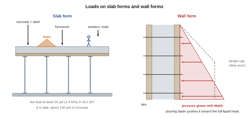
The dead load is the weight of the concrete, the reinforcing steel and the formwork itself. Normal-weight reinforced concrete weighs 150 lb/ft³ (about 2,400 kg/m³), so every 4 in (100 mm) of slab thickness adds 50 psf (about 2.4 kPa). The formwork, beams and plywood add a little more, often taken as 10 psf (about 0.5 kPa) for a typical slab system.
Live load from construction
The live load comes from workers, tools, hoses, equipment, and concrete that is heaped while it is being placed. ACI 347 sets a minimum construction live load for design, and ACI 347 in the United States recommends at least 50 psf (2.4 kPa), rising to 75 psf (3.6 kPa) where motorized carts are used, with a minimum total of 100 psf (about 4.8 kPa) for dead plus live load. These are minimums. A pile of rebar bundles, a stack of block, or a pump hose discharging in one spot can put far more load on a small area.
Impact and concentrated loads
Concrete dropped from a bucket or a hose lands with more force than its weight alone, and a heap of concrete forms where it lands before it is spread. Concentrated loads, such as a power trowel, a pallet of material or a crane-placed bundle, act on one beam or one shore rather than the whole deck. Good practice is to place concrete in layers from a low height and spread it at once, and never to land loads on the deck that the drawings do not allow for.
Lateral loads
Formwork also has to resist sideways forces: wind on wall forms and on the edge of decks, the push of concrete flowing during placement, the starting and stopping of buggies and pumps, and unbalanced pours that load one side of a form more than another. Bracing in two directions keeps a shoring system from racking sideways. Missing or loose bracing is one of the most common findings when shoring collapses are investigated.
Lateral pressure of fresh concrete
Wall and column forms carry the lateral pressure of fresh concrete. Fresh concrete behaves like a heavy liquid until it starts to stiffen, so the pressure on the form grows with depth. If the whole wall were filled faster than the concrete could stiffen, the pressure at the bottom would be the full liquid head: the density of the concrete times gravity times the depth. For a 10 ft (3 m) lift of normal concrete, that is 1,500 psf (about 72 kPa), about 2.4 times the water pressure at the same depth. Designers use formulas, such as those in ACI 347 and ACI 347, that reduce the design pressure when the rate of placement is slow, the concrete is warm and the mix stiffens normally. Those reductions only hold if the crew pours at or below the rate the designer assumed. Pouring a wall faster than the design rate, using a self-consolidating mix the design did not allow for, or vibrating deep into concrete that has already stiffened can push the pressure back up toward the full liquid head and burst the form.
Why formwork is engineered
OSHA's rule at 1926.703 requires formwork to be designed, fabricated, erected, supported, braced and maintained so that it will support, without failure, all vertical and lateral loads that may reasonably be anticipated. Drawings or plans, including all revisions, for the jack layout, formwork (including shoring equipment), working decks and scaffolds must be available at the jobsite. OSHA refers to ACI 347, the American Concrete Institute's guide to formwork for detail on design, and many project specifications require formwork and shoring drawings sealed by a professional engineer, especially for tall, multi-tier or reshored systems.
Engineering matters because formwork failures rarely have one cause. A shore that is slightly out of plumb, set on a sill that is a little soft, missing one brace, and loaded with a heap of concrete in one spot may hold each problem alone and fail when they combine. The engineer's design builds in a safety margin, and the drawings show exactly how the system must be built for that margin to exist. Every substitution, missing piece or extra load eats into it.
Reading the formwork drawings
Workers on the deck do not need to design formwork, but they should be able to read the drawings well enough to spot a difference between what is built and what is drawn. A typical slab shoring drawing at Cottonwood Place shows:
- the design loads: the slab thickness, the construction live load and any special loads such as a pump hose or a material landing area;
- the layout of beams and joists, with their spacing and the direction they span;
- the shore spacing in both directions and the shore model, with its rated capacity at the extension used;
- the bracing, with where it goes and how it attaches;
- the base details: what the shores sit on, such as the slab below, sills or mud sills on soil;
- the pour sequence and rate, where it matters;
- the stripping and reshoring requirements, including the concrete strength needed before forms come out;
- the engineer's seal, the date and the revision number.
The revision number matters. Drawings change as the design develops, and a crew building to an old revision may leave out shores the engineer added. Tallgrass keeps the current drawing set in the site trailer and on tablets, and the formwork foreman confirms the revision before every deck is built.
Shore capacity: why extension and spacing matter
An adjustable steel shore is strongest when it is short and loses capacity as it is extended, because a long slender post buckles more easily. Manufacturers publish load tables that give the safe working load at each extension. If the floor-to-floor height changes, or a crew extends a shore further to clear an obstruction, the capacity can drop below the load the drawing assumed. The same is true of spacing: moving a shore to make room for a pipe sleeve puts more load on its neighbors.
The program below checks the shores under a typical bay of the level 4 slab. It works out the load each shore carries from its tributary area, the area of deck it supports, and compares it with the manufacturer's rating at the extension used. The ratings are invented for this example.
# Shore check for a typical bay, US units (invented ratings; use the drawings and the manufacturer's tables).
slab_t = 8 / 12             # ft
concrete = 150.0            # lb/ft3 including rebar
forms = 10.0                # psf, beams, joists and plywood
live = 50.0                 # psf, construction live load
load = slab_t * concrete + forms + live      # psf on the deck
print(f"Design deck load: {load:.0f} psf")

rating = {8: 6300, 9.5: 5000, 11: 3600}       # lb safe working load by extension (ft), invented
for name, sx, sy, ext in [("drawn spacing", 5, 5, 9.5),
                          ("shore moved for sleeve", 7, 5, 9.5),
                          ("extra extension", 5, 5, 11)]:
    per_shore = load * sx * sy
    ok = "OK" if per_shore <= rating[ext] else "OVERLOADED"
print(f"{name:24} {per_shore:6.0f} lb vs {rating[ext]:,} lb at {ext} ft -> {ok}")Design deck load: 160 psf drawn spacing 4000 lb vs 5,000 lb at 9.5 ft -> OK shore moved for sleeve 5600 lb vs 5,000 lb at 9.5 ft -> OVERLOADED extra extension 4000 lb vs 3,600 lb at 11 ft -> OVERLOADED
Built as drawn, each shore carries well under its rating. Moving one shore to make room for a sleeve, or extending shores to reach a higher ceiling, puts the same shores over their rating, even though nothing looks wrong. This is why the rule on the deck is simple: build exactly what is drawn, and if something has to change, stop and ask the formwork foreman, who goes back to the engineer.
What workers on the deck can do
Most of the people who walk on a deck had nothing to do with its design, yet their actions decide whether the design holds. Before and during a pour, everyone on or under the deck can help:
- Keep loads where the drawings allow. Ask before landing material, and spread it out rather than stacking it in one spot.
- Leave the shoring alone. Do not borrow a shore for another job, knock out a brace to get a cart through, or lower a shore to fit a ladder under the deck.
- Watch the base. Shores on soil need sills on firm, level, compacted ground, and rain or thawing frost can soften that ground overnight. Report any sill that has sunk, tilted or been undermined.
- Report damage. A dented shore, a bent beam or a cracked base plate may no longer carry its rated load. Tag it and tell the formwork foreman.
- Speak up during a pour. Creaking, a beam deflecting more than its neighbors, plywood bulging, a shore head moving or concrete leaking from a joint can all be early signs of trouble. Anyone who sees them calls a stop.
These habits cost nothing, and they protect the margin the engineer built into the design.
Worked problem
The sleeve in the way
Show solution
- While building the level 4 deck, Lena Petrov finds that a mechanical sleeve lands exactly where a shore is drawn.
- Moving the shore 2 ft (600 mm) would clear the sleeve, and a carpenter suggests just doing it.
- Lena stops and calls the formwork foreman, who checks the drawing. Moving the shore increases the tributary area of two neighboring shores beyond their rating at that extension.
- The foreman phones the formwork engineer's office. The engineer issues a sketch adding an extra beam and two extra shores on either side of the sleeve, and the sketch is added to the drawing set as a revision.
- The deck is built to the sketch, and the inspection before the pour checks the added shores.
Answer: A small, sensible-looking change to shore layout can overload the system. Changes go through the formwork designer and are recorded as revisions.
Common mistakes
MistakeMoving, removing or substituting a shore because it is in the way.
InsteadBuild what is drawn; changes go back to the formwork designer as a revision.
MistakeLanding bundles of rebar or pallets anywhere on a deck.
InsteadLand loads only where the drawings allow and spread them out.
MistakePouring a wall as fast as the pump can deliver.
InsteadKeep to the pour rate the formwork design assumed.
MistakeBuilding from whatever drawing is in the gang box.
InsteadConfirm the current revision before building.
MistakeLeaving out bracing on short shores because they look stable.
InsteadInstall all bracing shown; it keeps the system from racking sideways.
Summary and key terms
- Formwork carries the dead load of concrete, steel and forms, construction live loads, impact and concentrated loads, and lateral loads.
- Wall and column forms carry lateral pressure from fresh concrete that grows with depth and with the rate of placement.
- OSHA 1926.703 requires formwork to support all reasonably anticipated loads and current drawings to be kept at the jobsite; ACI 347 gives the details.
- Shore capacity drops as shores are extended, and moving one shore loads its neighbors.
- Read the drawings for loads, layout, spacing, bracing, base details, pour rate, stripping requirements and revision.
- Build exactly what is drawn, and send any change back to the formwork designer.
- Falsework
- Temporary structure, such as shoring towers and frames, that supports formwork until the concrete can support itself.
- Dead load
- The weight of the concrete, reinforcing steel and formwork.
- Construction live load
- The load from workers, equipment, tools and heaped material during construction.
- Lateral pressure
- The sideways push of fresh concrete on wall and column forms, which increases with depth and placement rate.
- Tributary area
- The area of deck whose load is carried by one shore or beam.
- Rate of placement
- How fast concrete rises in a wall or column form, usually in meters or feet per hour.
Practice problems
Work each problem on paper first, then reveal the answer to check.
Name four kinds of load a slab form must carry.
Show answer
Dead load of concrete, steel and forms; construction live load; impact and concentrated loads; and lateral loads such as wind and unbalanced placement.
Why can pouring a wall too fast burst the form?
Show answer
Lateral pressure rises with the rate of placement; pouring faster than the design rate pushes the pressure toward the full liquid head.
A 10 in (250 mm) slab: about how much is its concrete dead load?
Show answer
About 125 psf (6.0 kPa), at 2.4 kPa per 100 mm (50 psf per 4 in).
Why does extending a shore reduce its capacity?
Show answer
A longer, more slender post buckles at a lower load.
What should a carpenter do if a shore is drawn where a sleeve must go?
Show answer
Stop and ask the formwork foreman, who gets a revised design from the engineer.
Lesson quiz · 5 questions
Score 60% or more to complete this lesson.
Create a free account to save your progress, take quizzes and earn a certificate.