
GEOM-300 · Lesson 8 of 12 · 20 min
Real-time kinematic positioning
Once the canal control was adjusted, the construction staking began. Grant Okonkwo's crew put stakes at every 20 m station along the centerline and at the top and toe of each slope, several hundred a day, each to about 2 cm horizontally and 3 cm vertically. There was no time for two-hour static sessions. They used real-time kinematic (RTK) positioning: carrier-phase relative positioning computed in the rover, second by second, from corrections streamed from a base or a network. RTK is what made GNSS the everyday instrument of surveying and construction, and also what made it easy to get centimeter-looking coordinates that are wrong. This lesson covers how it works, what limits it, and the procedures that keep it honest.
How RTK works
An RTK base receiver on a known point transmits its raw code and carrier-phase observations, together with its coordinates and antenna description, as RTCM 3 messages, typically once a second. The rover receives them by radio or through NTRIP over a mobile data link, forms double differences with its own observations, and solves for the baseline from the base to itself in real time. The solution starts as a float solution, then the rover resolves the double-differenced ambiguities on the fly, while moving, with a fast integer search and validation as in Lesson 7. Once the ambiguities are fixed and tracking continues without slips, every new epoch gives a centimeter-level position from that epoch's phases alone.
Time to first fix with modern multi-GNSS, multi-frequency receivers on baselines of a few kilometers is usually a few seconds to a minute. The rover's display shows the solution status: autonomous, DGNSS, float or fixed, together with precision estimates. Only fixed solutions should be used for survey work. When the rover passes under a bridge or a tree canopy and loses most satellites, it must reinitialize; good rovers also check new fixes against the previous ones and against the float solution to catch wrong fixes, which are more likely after a brief outage.
Precision and baseline length
Manufacturers specify RTK precision as a constant plus a part per million of the baseline length, typically 8 mm + 1 ppm horizontally and 15 mm + 1 ppm vertically, as one-sigma values per component. The constant comes from phase noise, multipath and antenna errors at both ends; the distance-dependent part comes from the residual ionospheric, tropospheric and orbit errors that do not cancel between the two sites. Beyond 10 to 20 km from a single base, the residual ionosphere also makes ambiguities harder to fix reliably, and initialization slows. On disturbed ionospheric days the practical limit shortens to a few kilometers. Height precision is worse than horizontal, for the geometric reasons of Lesson 4, and a height difference between base and rover also introduces tropospheric errors that the models only partly remove.
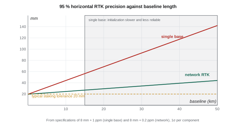
Network RTK
A network of permanent reference stations 50 to 70 km apart, with a central processor that resolves the ambiguities between the stations, can model the distance-dependent errors across the whole network area. Three ways of delivering the network's corrections are common. In the virtual reference station (VRS) approach the rover sends its approximate position to the server, which generates observations for a non-existent base close to the rover, so the rover processes as if over a short baseline. In the master–auxiliary concept (MAC) the server sends observations from one master station plus differences to nearby auxiliary stations, and the rover interpolates. With area correction parameters (FKP) the server broadcasts gradients of the errors across the area. All three let a rover anywhere inside the network work as if a base were a few kilometers away.
In Montana, the state operates the Montana State Reference Network (MTSRN), a statewide system of permanently located GNSS receivers run through the Montana State Library with partners including the Montana Department of Transportation, counties, tribal nations and others. It was free to use until July 2024 and has since been offered by subscription. Commercial networks also operate in the region. The essential question with any network is what coordinates its stations carry. A network aligned to NAD83(2011) epoch 2010.00 through the NOAA CORS Network gives rover positions in the national frame; a network tied to some other frame or epoch gives positions that differ by centimeters or more. NGS publishes guidelines for real-time networks, and the user should confirm the alignment of the network being used.
Base stations, coordinates and localization
A rover's position is only as good as the base coordinates. If the base is set up on a point whose coordinates are 5 cm in error, every rover position is 5 cm in error, with perfect precision. A common field practice, setting up a base over an unknown point and using its autonomous position, is acceptable only for work that is later shifted onto control, and it must never be mixed with work from a properly coordinated base. Base antenna height errors go straight into every rover height.
Many construction projects use a localization, also called a site calibration: the rover observes several control points with known project coordinates, and the software computes a transformation, usually a horizontal similarity transformation and a vertical inclined plane, from the GNSS frame to the project grid. A good localization uses at least four points surrounding the work area, and its residuals show how well the GNSS-derived positions agree with the control. Large residuals usually indicate a disturbed control point, a datum or epoch mismatch, or a blunder in the control coordinates, not a GNSS problem. Extrapolating a localization beyond the area of its control points can produce errors that grow rapidly with distance.
Field procedures and checks
Professional RTK practice is built on independent checks. At the start of each session, and again at the end, the rover observes a control point not used to set up the base or localization; the difference from its published coordinates must be within tolerance. Important points, such as control for structures, are observed twice, at different times with different satellite geometry, ideally more than an hour apart, and with a new initialization each time, so that a wrong fix or multipath does not repeat. Occupation times of a few seconds are enough for staking; for control points, 3 to 5 minutes of fixed epochs averaged together reduce noise and multipath. A tilt-compensating rover makes pole work faster, but its inertial sensor needs regular checks.
Guidelines for RTK work, such as the NGS user guidelines for single-base and network real-time positioning, express these practices as requirements: maximum baseline lengths, minimum satellites and maximum PDOP, number of independent occupations, check shots on control and maximum differences between repeats. They are summarized here as typical values, not as any one document's requirements: at least five or six satellites, PDOP below about 4, elevation mask 10° to 15°, repeat observations at least 45 minutes to a few hours apart, and agreement between repeats within about 2 cm horizontally and 3 cm vertically.
The program below tabulates the 95 % precision of single-base and network RTK against baseline length from typical specifications, then analyses ten three-minute occupations of control point CP7 observed on different days, comparing their mean and scatter with the published coordinates.
# RTK precision against baseline length, and a check of RTK shots on a control point
import math, statistics

def rtk_sigma(d_km, a_mm, b_ppm):           # manufacturer style: a + b ppm of baseline (1 sigma)
    return a_mm + b_ppm * d_km              # 1 ppm = 1 mm per km

print("baseline km  single-base H/V (mm, 95 %)   network RTK H/V (mm, 95 %)")
for d in (1, 5, 10, 20, 35, 50):
    sh, sv = rtk_sigma(d, 8, 1.0), rtk_sigma(d, 15, 1.0)
    nh, nv = rtk_sigma(d, 8, 0.2), rtk_sigma(d, 15, 0.3)   # the network models most distance-dependent error
    k = 2.45                                              # per-axis sigma to a 95 % circle
    print(str(d).rjust(8), "  ", format(k * sh, "6.0f"), format(1.96 * sv, "6.0f"), "              ", format(k * nh, "6.0f"), format(1.96 * nv, "6.0f"))

# Ten 3-minute RTK occupations of control point CP7 on different days and satellite geometries
published = (328614.487, 471208.913, 1022.604)   # northing, easting, orthometric height (m) on the project grid
shots = [(328614.479, 471208.921, 1022.618), (328614.495, 471208.905, 1022.587), (328614.490, 471208.917, 1022.611),
         (328614.471, 471208.909, 1022.629), (328614.486, 471208.926, 1022.598), (328614.502, 471208.911, 1022.592),
         (328614.483, 471208.900, 1022.623), (328614.488, 471208.919, 1022.606), (328614.478, 471208.914, 1022.640),
         (328614.493, 471208.908, 1022.601)]
for k, name in enumerate(("north", "east", "height")):
    v = [s[k] for s in shots]
    m, sd = statistics.mean(v), statistics.stdev(v)
    print(name.ljust(6), "mean minus published", format(1000 * (m - published[k]), "+5.1f"), "mm   std dev", format(1000 * sd, "4.1f"), "mm")
dh = [math.hypot(s[0] - published[0], s[1] - published[1]) for s in shots]
dv = [abs(s[2] - published[2]) for s in shots]
print("largest horizontal check", round(1000 * max(dh), 1), "mm; largest vertical check", round(1000 * max(dv), 1), "mm")
tol_h, tol_v = 0.020, 0.035
print("shots outside tolerance (20 mm H or 35 mm V):", sum(1 for a, b in zip(dh, dv) if a > tol_h or b > tol_v))baseline km single-base H/V (mm, 95 %) network RTK H/V (mm, 95 %)
1 22 31 20 30
5 32 39 22 32
10 44 49 24 35
20 69 69 29 41
35 105 98 37 50
50 142 127 44 59
north mean minus published -0.5 mm std dev 9.1 mm
east mean minus published +0.0 mm std dev 7.9 mm
height mean minus published +6.5 mm std dev 17.0 mm
largest horizontal check 16.5 mm; largest vertical check 36.0 mm
shots outside tolerance (20 mm H or 35 mm V): 1At 1 km from the base, the specification gives about 22 mm horizontal and 31 mm vertical at 95 %; at 20 km, 69 mm in both. A network keeps the horizontal figure below about 30 mm out to 20 km. The ten check occupations on CP7 have means within a millimeter of the published horizontal coordinates and 6.5 mm in height, with standard deviations of 8 to 9 mm horizontally and 17 mm vertically, which is good RTK performance. One occupation, the ninth, missed the 35 mm vertical tolerance by a millimeter; in practice it would be repeated. The scatter, not the mean, determines the confidence that any single stake is within tolerance.
Worked problem
Is RTK good enough for this task?
The canal's concrete turnout structures must be staked to ±20 mm horizontally at 95 %. The nearest permanent station is 18 km away. The rover specification is 8 mm + 1 ppm horizontal per component, 1 sigma. Can single-base RTK from that station meet the requirement? Would a local base 1.5 km away do so?
Show solution
- \[\sigma = 8 + 1 \times 18 = 26\ \text{mm per component}\]
- \[r_{95} = 2.45\,\sigma = 2.45 \times 26 = 64\ \text{mm} > 20\ \text{mm}\]
- \[\text{local base: } \sigma = 8 + 1.5 = 9.5\ \text{mm}, \quad r_{95} = 2.45 \times 9.5 = 23\ \text{mm}\]
Answer: Neither meets ±20 mm at 95 % on a single short occupation according to the specification. The 18 km baseline is hopeless; the local base is close. In practice the crew would use the local base on a well-coordinated control point, observe each structure point twice with averaging over 30 s or more, and check the results against each other and against a total station tie between structure points. For tighter tolerances still, a total station from GNSS-derived control is the right tool.
Heights from RTK
RTK gives ellipsoidal height differences. To obtain heights in the project's vertical datum, the rover applies a geoid model, as in GEOM-230, and in a localization a vertical adjustment absorbs any local offset. The geoid model must match the vertical datum and frame of the control; using the wrong model, or forgetting to load one, produces errors of decimeters to meters. For the canal, whose grades depended on centimeters, Ruth required every RTK height on structures to be checked against a leveled benchmark within the same session.
When RTK fails quietly
Most RTK errors are not random noise but blunders that look like good data: a wrong antenna height, a base on the wrong point, a project set to the wrong datum or geoid model, a wrong fix after an outage, or multipath from a nearby vehicle or wall. The rover's precision estimate cannot detect any of them. That is why checks on independent control, repeat observations with fresh initializations, and comparison with conventional measurements are part of every professional procedure, and why RTK results for control are documented with their base, network, epoch, geoid model and check results.
Common mistakes
MistakeUsing float solutions for staking.
InsteadUse only fixed solutions, and check them; float solutions can be wrong by decimeters.
MistakeSetting the base on an autonomous position and mixing with other work.
InsteadCoordinate the base on control, or shift the work onto control later and never mix.
MistakeExtrapolating a localization beyond its control points.
InsteadSurround the work area with at least four control points.
MistakeRepeating an occupation immediately.
InsteadRepeat at a different time with new geometry and a new initialization to catch wrong fixes and multipath.
MistakeIgnoring the frame and epoch of a real-time network.
InsteadConfirm the network's datum, realization and epoch match the project.
Summary and key terms
- RTK forms double differences in real time from base observations streamed by radio or NTRIP and fixes ambiguities on the fly.
- Precision is typically 8 mm + 1 ppm horizontal and 15 mm + 1 ppm vertical per component; reliability falls beyond 10–20 km from a single base.
- Network RTK models distance-dependent errors and delivers corrections through VRS, MAC or FKP.
- Rover positions inherit base coordinate and antenna height errors.
- Localizations fit GNSS positions to project control; residuals reveal control problems.
- Check shots on control and repeat occupations with new geometry are essential.
- Heights require the correct geoid model and checks against benchmarks.
- RTK
- Real-time kinematic positioning: carrier-phase relative positioning computed in real time in the rover.
- Time to first fix
- The time a rover needs to resolve ambiguities after starting or losing lock.
- Network RTK
- RTK using corrections modeled from a network of permanent reference stations.
- Virtual reference station
- Observations generated by a network server for a fictitious base near the rover.
- Localization
- A transformation fitted from GNSS-derived positions to project coordinates of control points.
- Check shot
- An independent observation of a known point to verify an RTK setup.
Practice problems
Work each problem on paper first, then reveal the answer to check.
A spec of 10 mm + 1 ppm: what is σ per component at 25 km?
Show answer
35 mm; 95 % horizontal radius about 86 mm.
A base is set 0.10 m too low in antenna height. What happens to rover heights?
Show answer
They are all 0.10 m too low.
Why repeat occupations at different times?
Show answer
To change satellite geometry and multipath and reinitialize, so wrong fixes do not repeat.
A localization has residuals of 3, 4, 2 and 41 mm. What should be done?
Show answer
Investigate the 41 mm point; it is likely disturbed or wrongly coordinated.
What three items must a network user confirm about network coordinates?
Show answer
The datum or frame, its realization and its epoch.
Lesson quiz · 5 questions
Score 60% or more to complete this lesson.
Create a free account to save your progress, take quizzes and earn a certificate.