
GAS-210 · Lesson 4 of 12 · 25 min
Installing and starting a furnace
▶ Video coming soon A video version of this lesson is on the way.
On Wednesday, October 21, Rosa's crew replaced a 1994 mid-efficiency furnace in a split-level house in Upper Arlington. The new furnace was a single-stage condensing model with an input of 70,000 Btu/h, chosen from a heat loss calculation rather than from the old plate, which had read 100,000 Btu/h. The old furnace had shared a masonry chimney with the water heater, and GAS-120 told what happened next: with the furnace gone, the water heater was left alone in a chimney far too big for it, and a liner was booked. This lesson follows the furnace part of that job from the morning's first look at the basement to the start-up sheet Rosa signed late in the afternoon.
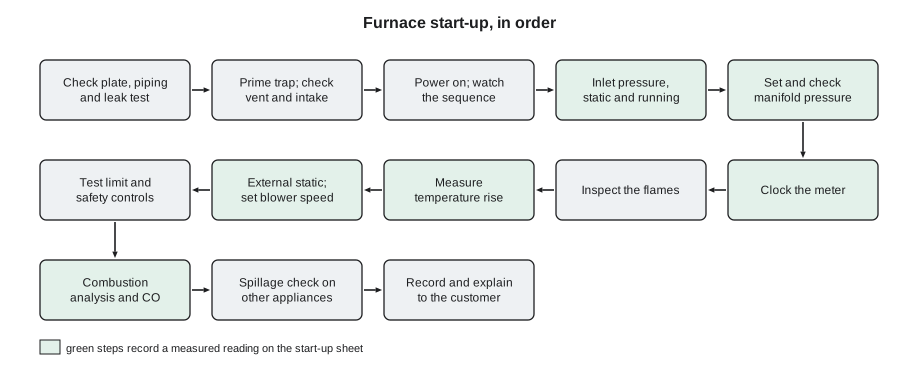
A furnace installation brings together everything a gas technician has learned so far: the code rules for location, clearances, piping and venting from GAS-120, the electrical work and its limits from GAS-130, and the appliance knowledge of the last three lessons. The appliance's installation instructions tie it all together. Bayline's start-up sheet follows the order in which the work is done, and so does this lesson.
Before the old furnace comes out
The work starts before anything is disconnected. Rosa's crew confirmed that the new furnace was the model on the work order, that its plate matched the house's gas (natural gas) and electrical supply, and that the heat loss calculation in the file had been done for this house. They measured the external static pressure of the existing duct system with the old furnace running, because a new furnace's blower can only deliver its rated airflow if the ducts allow it. They tested the old furnace's heat exchanger area and the house for carbon monoxide, noted the other gas appliances and their condition, and photographed the existing installation for the job file.
Removing the old furnace begins with shutting off its gas at the appliance valve, locking out its electrical supply and proving it dead as GAS-130 described, and disconnecting the vent, gas, electrical and duct connections. The open gas line is capped at once. The air-conditioning coil sitting on top of the old furnace is a refrigeration component; if it has to be removed or replaced, the refrigerant work is done by a technician certified to handle refrigerants, under the EPA's Section 608 rules, not by the gas crew. On this job the coil was nearly new and stayed in place, supported while the furnace under it was swapped.
Location, clearances and support
The new furnace must go where its instructions and the code allow, with the clearances to combustibles on its plate, and with enough space in front for service; the code and the instructions both set a minimum working space. It must sit level and solid, on a pad or base that keeps it off a damp floor, and a condensing furnace must be pitched exactly as its instructions say so the condensate drains. A furnace must not be installed where it is exposed to corrosive vapors, in a room the code prohibits, or where its combustion air would be contaminated. A furnace in a garage has its own rules, covered in lesson 9.
Return air needs particular care. The code does not allow return air to be drawn from a bathroom, kitchen, garage or a room containing another appliance whose combustion or draft could be upset, and the return system must be sealed so that it does not depressurize the furnace room. A leaky return beside an atmospheric water heater can pull flue gas out of the water heater's draft hood every time the blower runs. On the Upper Arlington job, Jonah found a panned return joist with an open end in the furnace room, an arm's length from the water heater; it was sealed with sheet metal and mastic before the furnace was started.
Gas piping at the furnace
The gas supply to a furnace follows the code rules from GAS-120. There must be a manual shut-off valve in the same room, accessible and within the distance the code sets, ahead of a union or a certified connector so the furnace can be removed. A sediment trap, or drip leg, is fitted ahead of the gas valve inlet to catch scale and liquids before they reach the valve; most furnace instructions require one even where the code would not. The pipe enters the cabinet through the knockout or grommet the instructions show, so that it cannot chafe or carry vibration. The piping is supported independently of the furnace, and the gas valve is never used to support the pipe or to take the torque of tightening a fitting.
Once the piping is connected, every new joint is tested for leaks. On a replacement, the house piping already in service is tested with a leak detection solution or an electronic detector at each new and disturbed fitting, with the system at its normal pressure; a new piping system or extension is pressure tested as GAS-120 described before it is put into service. The piping is then purged of air up to the appliance, in a ventilated area away from ignition sources, so that the burners light promptly rather than drawing air through the valve.
Venting, combustion air and condensate
The new furnace's vent and intake follow its instructions: the pipe material and sizes they list, within the maximum equivalent length, sloped back to the furnace, supported at the spacing they call for, and terminated with the clearances they and the code require. Where the old furnace's vent opening into the chimney is no longer used, it is sealed properly, and the remaining appliance in the chimney is checked, because the old furnace's flue gas no longer warms the chimney for it. That check is the reason Bayline's sheet has a line for every other appliance on the vent system. The condensate trap is primed and the drain is run to a suitable point; on this job a condensate pump was needed, and Bayline's electrical partner added its receptacle, as GAS-130 described.
First fire
With the gas, vent, drain and electrical connections complete, the furnace is started following the instructions' start-up section. The technician confirms the thermostat is wired correctly, powers the furnace and watches one full sequence from the call for heat to the blower starting. The first lights may take several tries if air remains in the line; that is normal, but a furnace that will not prove flame after the line is purged is shut down and checked, not reset again and again.
With the furnace running, the inlet pressure is measured at the gas valve's inlet tap with a manometer, first with the furnace off (static) and then with it running (dynamic), and ideally with every other gas appliance in the house running too. The reading must be within the plate's minimum and maximum inlet pressures. A large drop between static and running pressure points to undersized piping or a restriction. The manifold pressure is measured at the valve's outlet tap and adjusted, if needed, to the value on the plate, by the method the instructions give. On a two-stage furnace, both high-fire and low-fire pressures are checked.
| Measurement | Typical natural gas value | Where it is taken | What a wrong reading suggests |
|---|---|---|---|
| Inlet pressure, static | About 7 in. w.c. | Gas valve inlet tap, furnace off | Service regulator or utility issue |
| Inlet pressure, running | Not below the plate minimum | Inlet tap, all appliances on | Undersized or restricted piping |
| Manifold pressure, high fire | About 3.5 in. w.c. | Gas valve outlet tap | Valve out of adjustment, wrong valve |
| Manifold pressure, low fire | About 1.7 in. w.c. | Outlet tap, low stage | Wrong low-fire setting |
Next the input is checked by clocking the meter, as GAS-110 showed: with every other gas appliance off, time one revolution of the meter's test dial and calculate the gas flow, then the input. The measured input should be close to the plate input; most instructions allow a small difference, and a larger one means the manifold pressure, the orifices or the gas's heating value are not what was assumed. Finally the flames are inspected through the sight glass or burner opening: they should be steady, blue, sit on the burners, and enter the heat exchanger cleanly, without lifting, floating, yellow tips or rolling out.
Worked problem
Clocking the meter
Jonah times the meter's half-cubic-foot test dial at 26 seconds per revolution with only the new furnace running. The gas has a heating value of 1,000 Btu per cubic foot and the plate input is 70,000 Btu/h. What is the measured input?
Show solution
- Flow in cubic feet per hour:
- \[\frac{0.5 \ \text{ft}^3 \times 3600 \text{ s/h}}{26 \text{ s}} = 69.2 \ \text{ft}^3\text{/h}\]
- Input:
- \[69.2 \ \text{ft}^3\text{/h} \times 1000 \ \text{Btu/ft}^3 = 69\,200 \text{ Btu/h}\]
Answer: The measured input is 69,200 Btu/h against a plate input of 70,000 Btu/h, about 1 in 100 low and well within the instructions' allowance. Jonah recorded the dial size, the time and the result.
Airflow: temperature rise and static pressure
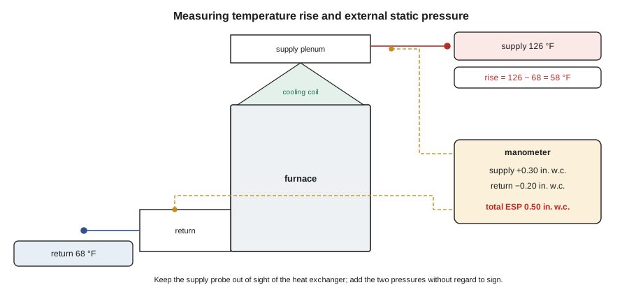
Once the furnace has run for several minutes and its temperatures are steady, the temperature rise is measured: the difference between the air temperature in the supply plenum, taken just past the heat exchanger but out of its line of sight so radiant heat does not affect the probe, and the air temperature in the return, just before the furnace. The rise must fall inside the range on the plate. Too high a rise means too little airflow: the heat exchanger runs hot, the limit may trip and the heat exchanger may crack. Too low a rise means too much airflow: the flue gas may cool too much in a mid-efficiency furnace, and the house gets drafts of lukewarm air.
The external static pressure is measured with a manometer across the furnace: one probe in the supply plenum, beyond the coil if one is fitted, and one in the return just before the furnace, adding the two readings without regard to sign. It must not exceed the maximum on the plate. If the rise is outside the range or the static pressure too high, the blower speed is changed using the taps or settings the instructions describe, and the measurements are repeated. If no setting brings both into range, the duct system is the problem, and the customer is told before the job is closed.
Worked problem
Checking temperature rise and static pressure
At the new furnace, Jonah reads a supply temperature of 126 °F and a return of 68 °F. His manometer reads +0.30 in. w.c. in the supply and −0.20 in. w.c. in the return. The plate gives a rise range of 40 to 70 °F and a maximum external static pressure of 0.50 in. w.c. Are both in range?
Show solution
- Temperature rise:
- \[126 - 68 = 58 \ ^\circ\text{F}\]
- External static pressure, adding the readings without regard to sign:
- \[0.30 + 0.20 = 0.50 \text{ in. w.c.}\]
Answer: The rise of 58 °F is inside the range. The static pressure of 0.50 in. w.c. is exactly at the maximum, which leaves no margin for a dirty filter; Rosa noted it and recommended a larger filter rack to the customer.
Safety controls, combustion and other appliances
Before leaving, the technician checks that the safety controls work as the instructions describe: for example, that the furnace shuts down when the thermostat call ends, when the door switch is opened and, where the instructions call for it, when the airflow is restricted enough to open the limit. A combustion analysis with a calibrated analyzer is taken in the vent at the test port the instructions show, recording oxygen or carbon dioxide, flue gas temperature and air-free carbon monoxide, and compared with the instructions' acceptable ranges; GAS-230 covers how. The CO reading in the house air is checked too.
Then the other appliances are checked. On the Upper Arlington job, the water heater now sat alone in the chimney, so Rosa ran a spillage test under worst-case conditions: every exhaust fan and the dryer running, the furnace blower on and interior doors set to depressurize the furnace room as much as possible. With the water heater firing, she held a smoke pencil and a mirror at its draft hood. It kept spilling well past the short start-up period the instructions allow, and the draft never established properly. That is an unsafe condition. Rosa shut the water heater off, tagged it out of service as Bayline's procedure requires, explained to the owners why, and called Priya, who moved the chimney liner job up to the next morning. The family went one night without hot water; the liner went in on the Thursday, and the water heater passed the same worst-case test before it was relit
Paperwork and the customer
The start-up sheet is the record of the installation. It lists the model and serial numbers, the gas type, the inlet and manifold pressures, the clocked input, the temperature rise, the external static pressure, the combustion analysis, the CO readings, the clearances, the vent material and length, and the checks of other appliances. In Columbus, Bayline's office pulls a mechanical permit before the work starts, and the start-up sheet goes in the file for the city inspection. The customer is shown how to change the filter, where the shut-off valves are, what the CO alarm does and what to do if it sounds, and is given the instructions to keep with the furnace.
Common mistakes
MistakeChoosing the new furnace by matching the old plate.
InsteadSize from a heat loss calculation and the measured duct static pressure.
MistakeLeaving the gas valve to take the twist of tightening the pipe.
InsteadHold the valve with a backup wrench and support the pipe independently.
MistakeMeasuring supply temperature where the probe can see the heat exchanger.
InsteadPlace the probe out of the line of sight of the heat exchanger.
MistakeSkipping the check of other appliances after a furnace change.
InsteadTest any appliance left on the old vent for spillage under worst-case conditions.
MistakeResetting a furnace again and again when it will not prove flame.
InsteadAfter purging the line, stop and diagnose.
Summary and key terms
- Before removal, confirm the model, gas and sizing, measure the duct static pressure, test for CO and record the existing installation; refrigerant work on a coil belongs to a certified refrigeration technician.
- Install the furnace level, with its clearances, service space, sealed returns, a manual shut-off valve, union and sediment trap, and independently supported piping.
- Leak test new joints and purge the line.
- Vent, intake and condensate follow the instructions.
- At start-up, watch the sequence; check inlet pressure static and running, manifold pressure and clocked input; inspect the flames; measure temperature rise and external static pressure and adjust blower speed; check safety controls and combustion; and test other appliances on the old vent for spillage.
- Record everything on the start-up sheet and explain the system to the customer.
- External static pressure
- The total resistance of the duct system outside the furnace, measured across the supply and return.
- Temperature rise
- The difference between supply air and return air temperatures across a furnace.
- Sediment trap
- A capped pipe nipple below the gas inlet that collects scale and liquid before the gas valve.
- Manifold pressure
- The gas pressure delivered by the gas valve to the burner orifices.
- Clocking the meter
- Timing the meter dial to calculate an appliance input from the gas flow.
- Spillage test
- A check that flue gas does not escape from a draft hood under worst-case house depressurization.
- Start-up sheet
- The written record of an installation and its measured settings.
Practice problems
Work each problem on paper first, then reveal the answer to check.
Why measure the duct static pressure before choosing the new furnace?
Show answer
The blower can only deliver its rated airflow if the duct system allows it.
Where is manifold pressure measured?
Show answer
At the gas valve's outlet pressure tap.
What does a temperature rise above the plate range indicate?
Show answer
Too little airflow across the heat exchanger.
A manometer reads +0.25 in. w.c. in the supply and −0.18 in. w.c. in the return. What is the external static pressure?
Show answer
0.25 + 0.18 = 0.43 in. w.c.
Why is the water heater checked after the furnace is replaced?
Show answer
It may be left alone in a vent sized for both, and may spill under worst-case conditions.
Lesson quiz · 5 questions
Score 60% or more to complete this lesson.
Create a free account to save your progress, take quizzes and earn a certificate.