
FAT-330 · Lesson 7 of 12 · 20 min
Control unit, power and circuit verification
Field devices tell you whether the edges of the system work. The control unit, its power and its circuits tell you whether the middle does. On the fourth day Gerry takes Sasha to the north wing's electrical room, where the wing's control unit sits beside its two remote power supplies, RPS-3 and RPS-4. 'Everything out there depends on this cabinet,' he says. 'We'll make every circuit fail, one way at a time, and we'll make the building lose power. Then we'll know.' This lesson covers verification of the control unit's functions, the circuits' fault behavior, and the primary and secondary power supplies.
The control unit itself
The tester starts by inspecting: the control unit is the listed model on the drawings, in the location shown, with clear working space in front, the cabinet secured, the wiring neat and identified, and the operating instructions posted. The software version and the program's date or checksum are recorded, because they define the system that is being verified; any change after today means retesting what the change affects.
Then every function is operated and its result observed:
- Each indicator lamp and the display segments, using the panel's lamp test.
- The alarm, supervisory and trouble signals, each produced by a real device, showing the correct type, point and description.
- Acknowledge, silence and reset, including the rule that a new alarm after silencing must re-sound the signals.
- Positive alarm sequence on the inpatient floors: the alarm is displayed at the staffed location, staff must acknowledge within 15 seconds, and if they don't reset within the investigation period of up to 180 seconds the general alarm sounds; a second detector or a manual station sounds it at once.
- Event history and printer, if fitted, recording each event with the right date and time.
- The network: the north wing node reports every event to the main panel in the hospital's main entrance, and the main panel's commands, such as silence and reset, reach the north wing.
# Check timed functions of the control unit against the sequence of operation
tests = [("positive alarm sequence acknowledge", 15, 15, 1), ("investigation period", 180, 178, 5), ("door holder release delay", 0, 1, 2), ("signal re-sound after silence + new alarm", 0, 2, 3)]
for name, design, measured, tol in tests:
    ok = abs(measured - design) <= tol
print(f"{name:34s} design {design:4d} s, measured {measured:4d} s {'ok' if ok else 'CHECK PROGRAMMING'}")positive alarm sequence acknowledge design 15 s, measured 15 s ok investigation period design 180 s, measured 178 s ok door holder release delay design 0 s, measured 1 s ok signal re-sound after silence + new alarm design 0 s, measured 2 s ok
Circuit fault tests
Every circuit the control unit supervises must report faults, and circuits of higher classes must also keep working through them. The tester proves both, circuit by circuit, by creating each fault at the far end or the middle of the circuit and watching the result.
| Fault created | Class B circuit | Class A circuit | Class X or isolated loop |
|---|---|---|---|
| Single open | Trouble; devices beyond the open lost | Trouble; all devices still work | Trouble; all devices still work |
| Ground fault | Ground fault trouble; circuit works | Ground fault trouble; circuit works | Ground fault trouble; circuit works |
| Wire-to-wire short | Trouble or alarm as designed; circuit may fail | Trouble; circuit may fail | Trouble; isolators limit the loss to one section |
On the north wing the signaling line circuits are Class A with fault isolators, and the notification appliance circuits are Class B. Sasha opens each loop at its midpoint and confirms that every device on both sides still reports; she grounds each conductor in turn and confirms the ground fault trouble; and on each loop she shorts the conductors between two isolators and confirms that only the devices in that section are lost. Each test is done for every loop, not one loop as a sample.
This is where the L3 loop finding from the installation review is proven corrected. In FAT-220 its outgoing and return legs had been found running together in the same J-hooks, which defeats the point of Class A. They were rerouted along the south corridor. Sasha now confirms the loop survives an open, and Gerry walks the route above the ceiling with the drawings to confirm the two legs are separated as the design requires.
Primary power
The control unit and each remote power supply must be fed from a dedicated branch circuit, with the breaker identified, marked and protected against being switched off by accident, as the installation standard requires. The tester checks the panelboard labels, the breaker lock and the circuit's source; on a hospital the fire alarm is fed from the essential electrical system so that it stays on generator power. Sasha checks that the circuit numbers on the fire alarm drawings match the panelboard schedules, and that each panel's AC trouble operates when its breaker is opened.
Secondary power: proving the batteries
The batteries must run the system for the required time without primary power: a standby period with the system in normal condition, followed by an alarm period with all the notification appliances and outputs operating. The designer's battery calculation sets the capacity; verification proves that the calculation reflects what was actually installed and that the batteries deliver.
Sasha's procedure for each power supply is:
- Check the battery type, capacity and date against the calculation and the panel's listing, and that all batteries in a set are the same type, capacity and age.
- Measure the charger's float voltage with the battery connected.
- Open the primary supply breaker and confirm the AC trouble, then measure the standby current drawn from the battery.
- Put the system into alarm on battery power and measure the alarm current and the battery voltage under load.
- Compare the measured currents with the calculation, and recalculate if they are higher.
# Verify a battery calculation against measured currents (RPS-4)
standby_h, alarm_h = 24, 0.08333333333333333
factor = 1.2                      # design margin from the calculation
calc = {"standby_A": 0.28, "alarm_A": 6.60}
measured = {"standby_A": 0.32, "alarm_A": 7.90}
installed_Ah = 18.0
def need(c): return (c["standby_A"] * standby_h + c["alarm_A"] * alarm_h) * factor
print(f"capacity needed from the design calculation: {need(calc):5.1f} Ah")
print(f"capacity needed from measured currents:      {need(measured):5.1f} Ah")
print(f"installed: {installed_Ah} Ah ->", "adequate" if installed_Ah >= need(measured) else "TOO SMALL - recalculate and replace")capacity needed from the design calculation: 8.7 Ah capacity needed from measured currents: 10.0 Ah installed: 18.0 Ah -> adequate
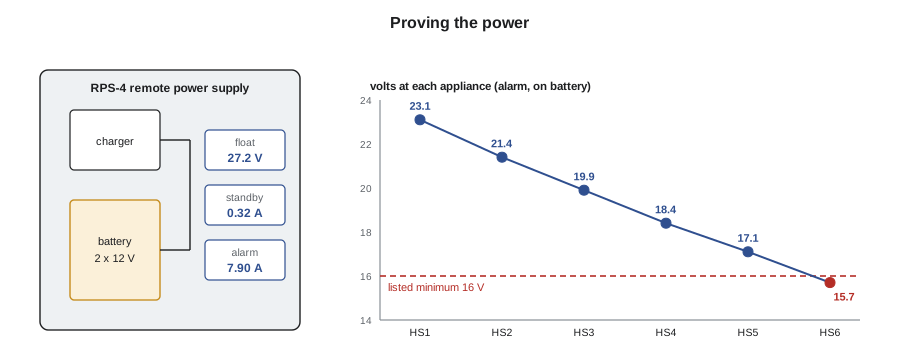
RPS-4's measured alarm current is higher than the calculation because of the medication room strobes added in drawing revision 4. With 24 hours of standby and the five minutes of alarm NFPA 72 requires for a system without voice, the 18 Ah batteries still have enough capacity, but the margin is smaller than the design shows. Ravi updates the calculation on the record drawings so that the next technician sees the true load. If the alarm period were longer, as for a voice system, the batteries would have been too small; that is why verification measures rather than assumes.
Notification circuits under load
A notification appliance circuit must deliver enough voltage at its last appliance, with every appliance on the circuit operating, while the system runs on its batteries at their lowest allowed voltage. Appliances listed for 24 V nominal systems are typically listed to operate down to 16 V. The tester measures the voltage at the end of each circuit with the circuit in alarm, first on primary power and then on battery, and compares it with the appliances' listed minimum and with the designer's voltage drop calculation.
# End-of-circuit voltage on each notification appliance circuit, in alarm on battery
min_listed = 16.0
circuits = {"N3-1": 19.8, "N3-2": 18.9, "N4-1": 20.4, "RPS-3 NAC 1": 18.1, "RPS-3 NAC 2": 17.6,
            "RPS-4 NAC 1": 16.4, "RPS-4 NAC 2": 15.7}
for c, v in circuits.items():
    margin = v - min_listed
    note = "ok" if margin >= 1.0 else ("low margin - review" if margin >= 0 else "FAIL - below listed minimum")
print(f"{c:12s} {v:5.1f} V margin {margin:+4.1f} V {note}")N3-1 19.8 V margin +3.8 V ok N3-2 18.9 V margin +2.9 V ok N4-1 20.4 V margin +4.4 V ok RPS-3 NAC 1 18.1 V margin +2.1 V ok RPS-3 NAC 2 17.6 V margin +1.6 V ok RPS-4 NAC 1 16.4 V margin +0.4 V low margin - review RPS-4 NAC 2 15.7 V margin -0.3 V FAIL - below listed minimum
RPS-4 NAC 2 fails on battery and NAC 1 has almost no margin. Both carry the fourth-floor appliances, including those added in revision 4. The fix is to move six appliances from NAC 2 to a spare circuit on RPS-3, which Ravi approves on a marked-up drawing. After the change, both circuits are remeasured, the battery calculations for both supplies are revised, and the RPS-3 batteries, which now carry more load, are checked again.
The link to the signal receiving center
The fire alarm must transmit alarm, supervisory and trouble signals to the supervising station that monitors the hospital. The tester confirms with the station, by phone and from the station's own log, that each signal type arrived with the right account and zone information, and that a failure of each communication path produces a trouble at both ends. At Eastview the north wing reports through the hospital's main panel, so the test proves both the network and the main panel's transmission of north wing events.
Worked problem
A trouble that wouldn't clear
After the battery test on RPS-3, the panel shows a battery trouble that doesn't clear when the primary supply is restored. The battery voltage reads 25.9 V on float. What should Sasha check?
Show solution
- Whether the trouble is latching and needs a reset; some panels hold battery troubles until reset.
- Whether the charger has gone into a slow recharge after a deep discharge, and the panel is reporting low charge current; waiting and rechecking within the recharge time the standard allows is reasonable.
- Whether a battery connection was disturbed during the test; a loose lead can show normal voltage with no current flowing.
- If none explain it, record a failure and have the installer check the charger, then retest.
Answer: Restoration is part of every test: the system must return to normal by itself.
Annunciators and remote displays
The north wing's annunciator, in the heated inner vestibule at the fire department entrance where the installation review had it moved, is verified like a small control unit. Each alarm, supervisory and trouble signal from the wing must appear on it with the same description as at the panel; its lamp test must work; its silence and acknowledge keys, if enabled, must do what the sequence says; and removing its communication link must produce a trouble at the panel. Captain Strand had asked for an oriented floor plan beside it, and Sasha checks that the plan matches the building and the descriptions, including the rooms renamed in drawing revision 4.
Remote displays at the hospital's security desk are part of the network, so they are verified too: every north wing event must reach them with the correct text. The hospital's building automation screen also shows fire alarm events through an interface, but it isn't part of the listed fire alarm system. Its information is checked and any errors are reported, but a fault there is recorded separately, because the fire alarm's required functions don't depend on it.
Time-stamping and the event history
At the end of the panel tests Sasha prints the panel's event history for the day and compares it with her own log. Every test she performed should be there with the right point, the right type and a time within a minute or two of her record. Missing events or wrong times mean the history can't be trusted later, when someone needs to know what the system saw during a real incident. The panel clock is set to the hospital's time standard, and its daylight-saving setting is checked.
Common mistakes
MistakeTesting one loop's fault behavior as a sample.
InsteadTest opens, grounds and shorts on every circuit.
MistakeTrusting the battery calculation without measuring.
InsteadMeasure standby and alarm current and recalculate if they are higher.
MistakeMeasuring end-of-circuit voltage on primary power only.
InsteadMeasure in alarm on battery, the worst case.
MistakeForgetting the remote power supplies.
InsteadEach one is verified like the main panel: power, batteries, circuits.
MistakeAccepting a monitoring test without confirming with the center's log.
InsteadConfirm every signal type arrived with the right information.
Summary and key terms
- Record the control unit's software version and program identity before testing.
- Operate every function, including silence, reset and the timed sequences.
- Create opens, grounds and shorts on every circuit and compare with the class's expected behavior.
- Check primary power: dedicated, marked, protected and on the essential supply in a hospital.
- Measure standby and alarm currents, and prove the batteries against the real load.
- Measure each notification circuit's end voltage in alarm on battery.
- Float voltage
- The voltage a charger holds a fully charged battery at.
- Standby current
- The current the system draws in normal condition on battery.
- Alarm current
- The current drawn with all notification appliances and outputs operating.
- Fault isolator
- A device that disconnects a shorted section of a loop so the rest keeps working.
- Class A
- A circuit that keeps working beyond a single open.
Practice problems
Work each problem on paper first, then reveal the answer to check.
Why record the software version before testing?
Show answer
It defines the system being verified; later changes must be retested.
What should a Class A loop do when opened mid-loop?
Show answer
Keep every device on both sides working and report a trouble.
Why measure battery currents instead of trusting the calculation?
Show answer
Changes during construction may have increased the load.
Under what condition is end-of-circuit voltage measured?
Show answer
With the circuit in alarm, running on battery.
How is the monitoring link verified?
Show answer
By confirming each signal type in the receiving station's log, and testing each path's failure.
Lesson quiz · 5 questions
Score 60% or more to complete this lesson.
Create a free account to save your progress, take quizzes and earn a certificate.