
FAT-330 · Lesson 5 of 12 · 20 min
Pre-testing and readiness
Bramwell's installation foreman, Kyle Brandt, reports on a Friday afternoon that the north wing is ready for the acceptance test on Monday. Gerry asks for one thing: 'Send me the pre-test records.' On Monday morning they haven't arrived, and Gerry spends the first hour walking the third floor with Kyle instead of testing. They find a ceiling still open over the nurses' station, two detectors with their dust covers on, a manual station hanging by its wires and a junction box without a cover. 'This is why we ask,' Gerry says. 'Pre-testing is the installer's job, and readiness is something you prove, not something you announce.' This lesson covers what pre-testing involves and how a tester decides that a system is ready for its acceptance test.
What the installer's pre-test covers
Pre-testing is the installer's own check that the system is complete and working before anyone else tests it. It is not a lighter version of the verification; it is a different job. The installer is looking for faults to fix. The tester is proving that none are left. A thorough pre-test includes:
- Insulation resistance tests on every circuit before devices are connected, to find damaged insulation and conductors touching a box or a grounded raceway.
- Continuity tests of every circuit, and for Class A circuits a check that both the outgoing and return paths are complete.
- Checks of every termination, every device base, every end-of-line device and every splice.
- Addressing of every addressable device, and a check that the panel sees every address with the correct device type.
- Loading the final program and confirming the sequence of operation runs as designed.
- Operating every device at least once to prove it reports to the panel.
- Measuring voltages on notification appliance circuits with the appliances operating.
The pre-test produces a record: circuit test results, a list of devices operated, faults found and corrected, and a signed statement that the system is complete and ready. The tester reviews it before accepting the system for testing.
Insulation resistance and ground faults
Insulation resistance testing uses a megohmmeter, which applies a test voltage, typically 500 V for low-voltage circuits, between conductors and between each conductor and ground, and reads the resistance. It must be done before devices and the panel are connected, because the test voltage can damage electronic devices and the control unit. A healthy new cable reads in the hundreds or thousands of megohms. A low reading means damaged insulation, moisture in a box, or a conductor nicked during pulling.
Ravi's specification for the north wing asks for at least 20 megohms on every conductor to ground and between conductors, and for any circuit reading lower to be investigated even if the panel later shows no ground fault. The panel's ground fault detection only trips at a much lower resistance; a cable reading 2 megohms won't make the panel complain today, but it is on its way to failing in a wet season.
# Review the installer's insulation resistance records against the specification
minimum_megohms = 20
readings = [("SLC L1 out", 2000), ("SLC L1 return", 1800), ("SLC L2 out", 950), ("SLC L2 return", 1100),
            ("SLC L3 out", 1400), ("SLC L3 return", 14), ("NAC N3-1", 780), ("NAC N3-2", 2.5),
            ("NAC N4-1", 1200), ("RPS-3 NAC 1", 600), ("RPS-4 NAC 2", 0.8)]
for circuit, r in readings:
    if r < 1:
        verdict = "FAIL - near ground fault, find and repair before verification"
    elif r < minimum_megohms:
        verdict = "below specification - investigate"
    else:
        verdict = "ok"
    print(f"{circuit:15s} {r:7.1f} Mohm  {verdict}")
low = [c for c, r in readings if r < minimum_megohms]
print("circuits to correct before verification:", ", ".join(low))SLC L1 out 2000.0 Mohm ok SLC L1 return 1800.0 Mohm ok SLC L2 out 950.0 Mohm ok SLC L2 return 1100.0 Mohm ok SLC L3 out 1400.0 Mohm ok SLC L3 return 14.0 Mohm below specification - investigate NAC N3-1 780.0 Mohm ok NAC N3-2 2.5 Mohm below specification - investigate NAC N4-1 1200.0 Mohm ok RPS-3 NAC 1 600.0 Mohm ok RPS-4 NAC 2 0.8 Mohm FAIL - near ground fault, find and repair before verification circuits to correct before verification: SLC L3 return, NAC N3-2, RPS-4 NAC 2
Three circuits fail the specification. Kyle's installers find the causes: a return leg of loop L3 pinched under a cable tray bracket, a notification circuit on the third floor with water in a back box under a leaking roof drain, and a remote supply circuit with a staple through the cable above the penthouse ceiling. All three are repaired and retested before Sasha begins.
Ceilings, dust and covers
Smoke detectors installed before the building is clean collect construction dust, which raises their sensitivity until they false alarm, or lowers it as dust clogs the chamber. Most manufacturers supply dust covers and insist they stay on until construction cleaning is finished, then come off before testing. A detector tested with its cover on is useless as a test; a detector left with its cover on after testing is disabled. The readiness walk checks both.
Ceilings matter for the same reason and another: a detector mounted on an open ceiling grid isn't in its final position, and the space above may later be closed off in a way that changes airflow. The tester tests detectors only on finished ceilings. On the north wing, the third-floor nurses' station ceiling is closed on Tuesday, and its four detectors move to Wednesday's list.
Covers matter for safety and for supervision. Junction boxes without covers, manual stations hanging on their wires and open panel doors are hazards to the people testing and signs that the installation isn't finished. Gerry's team doesn't test an area with open boxes; it records the area as not ready and moves on.
Documents on site
The tester also checks that the documents needed for testing are on site and current. A test that compares devices against superseded drawings proves nothing. Before day one, Sasha checks the revision of every drawing against the designer's transmittal, confirms the sequence of operation matches the program loaded in the panel, and confirms that the battery and voltage drop calculations reflect the devices actually installed, not those in the original design.
# Readiness checklist: can verification start on this floor?
checks = {
    "installer pre-test record received": True,
    "insulation resistance records reviewed": True,
    "ceilings closed where detectors are mounted": False,
    "construction cleaning complete, dust covers removed": True,
    "all device covers and box covers installed": True,
    "final program loaded and matches sequence of operation": True,
    "current drawings and calculations on site": True,
    "access arranged for locked rooms": True,
}
open_items = [k for k, v in checks.items() if not v]
for k, v in checks.items():
    print(("ready   " if v else "NOT YET ") + k)
print("start verification" if not open_items else f"floor not ready: {len(open_items)} item(s) open")ready installer pre-test record received ready insulation resistance records reviewed NOT YET ceilings closed where detectors are mounted ready construction cleaning complete, dust covers removed ready all device covers and box covers installed ready final program loaded and matches sequence of operation ready current drawings and calculations on site ready access arranged for locked rooms floor not ready: 1 item(s) open
The program and the sequence of operation
A fire alarm's behavior lives in its program. Before verification, the installer loads the final program and the tester gets a printout or file showing every point, its description, its type and the outputs it controls. Sasha compares it with the sequence of operation line by line. On the north wing she finds two problems that would otherwise have surfaced only during integrated testing: the duct detector for AHU-N2 is programmed to shut down AHU-N1, and the stair 4N door release is mapped to the wrong relay, the same fault the installation review found in FAT-220, reintroduced when the programmer reloaded an older file. Both are corrected and the program's version and date are recorded, so that any later change will be visible.
Keeping the program under control during verification is important. If the installer's programmer changes the program halfway through testing, every function the change affects must be retested, and the tester needs to know it happened. Gerry's rule is that program changes during verification are made only with his knowledge, and each change is recorded with the reason and the functions retested.
Accepting the system for verification
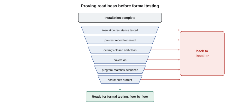
When the pre-test record is complete, the insulation tests are acceptable, the floors are physically ready and the documents are current, the tester accepts the system, or a defined part of it, for verification. On a large building this often happens floor by floor. Accepting means the tester's clock starts; finding a pre-test-level fault after acceptance (a device with no address, a missing end-of-line resistor) is recorded as a verification failure, and repeated failures of that kind are a sign that the system wasn't really ready.
Some contracts make the installer pay for the tester's time when the system isn't ready. Even where they don't, recording the not-ready conditions in writing protects the tester and shows the owner why the schedule slipped.
Worked problem
Monday on the third floor
Gerry's readiness walk of the third floor finds: an open ceiling over the nurses' station (4 detectors), 2 detectors with dust covers on, a manual station hanging by its wires, a junction box without a cover, and no pre-test record. The rest of the floor looks complete. What should he do?
Show solution
- Record each item in writing and give the list to the installer.
- Don't start verification on the third floor today; without a pre-test record the floor isn't accepted.
- Move the crew to a floor that is ready, if there is one, or to panel and power tests that don't depend on the third floor.
- Once the pre-test record arrives and the items are corrected, walk the floor again and accept it.
- Test the four nurses' station detectors only after the ceiling is closed.
Answer: The time spent proving readiness saves days of verifying an unfinished system.
A pre-test record worth trusting
Not all pre-test records are equal. Some are a signed sheet saying 'all tested OK'. Others list every circuit with its insulation readings, every device with the date it was operated and every fault with its correction. Gerry treats the first kind as a statement, not a record. When he receives one, he asks the installer to walk a floor with him and operate a sample of devices; if more than one or two fail, he asks for a real pre-test before verification continues. The good kind of record speeds verification, because the tester can plan knowing which areas had problems and test them first.
Pre-test records also help after handover. When a circuit develops a ground fault two years later, its original insulation reading shows whether the insulation has deteriorated or was marginal from the start. Sasha attaches the installer's circuit test records to the acceptance test record as an appendix for that reason, though the standard doesn't require it.
Readiness of the other systems
The fire alarm isn't the only system that must be ready. Before the trade-dependent tests in week two, Sasha confirms that the sprinkler system is filled, flushed and has passed its own hydrostatic test; that the air handlers have been started up and balanced; that the elevators have their inspection certificates or at least their acceptance inspection scheduled; that the door hardware is installed and powered; and that the generator has passed its own load test. A fire alarm interface test against a system that doesn't work yet tests nothing, and the other trade's own commissioning comes first.
Readiness is also a matter of safety for the verification crew. Live electrical panels must be closed, scaffolding and lifts must be inspected, and areas where other trades are still working overhead must be avoided. A tester's ladder in a corridor where the drywall crew is moving sheets is an accident waiting to happen, so the daily plan coordinates who works where.
Common mistakes
MistakeStarting verification because the installer says the system is ready.
InsteadAsk for the pre-test record and walk the area first.
MistakeMeggering circuits with devices and the panel connected.
InsteadDisconnect devices and the panel first; the test voltage can damage electronics.
MistakeAccepting low insulation readings because the panel shows no ground fault.
InsteadInvestigate anything below the specification; it will get worse.
MistakeTesting detectors with dust covers on or on open ceilings.
InsteadTest only clean, finished, uncovered detectors.
MistakeLetting the program change during verification without notice.
InsteadRecord every change and retest what it affects.
Summary and key terms
- Pre-testing is the installer's job and produces a written record.
- Insulation resistance tests are done before devices and the panel are connected.
- Low readings are investigated even if the panel shows no ground fault.
- Detectors are tested only on closed ceilings, after cleaning, with covers removed.
- The program is checked against the sequence of operation before testing.
- The tester accepts the system, or part of it, for verification only when readiness is proven.
- Pre-test
- The installer's checks to find and correct faults before formal testing.
- Insulation resistance
- The resistance between conductors, or between a conductor and ground, measured with a megohmmeter.
- Megohmmeter
- An instrument that measures high resistances using a test voltage.
- Dust cover
- A cover fitted to a new detector during construction to keep dust out.
- Sequence of operation
- The design document describing what the system does for each input.
Practice problems
Work each problem on paper first, then reveal the answer to check.
Why must devices be disconnected for insulation resistance testing?
Show answer
The megohmmeter's test voltage can damage electronic devices and the panel.
Why investigate a 2 megohm reading if the panel shows no fault?
Show answer
The insulation is damaged or wet and is likely to fail later.
Why test detectors only after construction cleaning?
Show answer
Dust affects their sensitivity and the test result.
What should the tester do if the program changes during testing?
Show answer
Record the change and retest every function it affects.
What does accepting a floor for verification mean?
Show answer
The tester is satisfied it is ready; faults found afterwards are recorded as verification failures.
Lesson quiz · 5 questions
Score 60% or more to complete this lesson.
Create a free account to save your progress, take quizzes and earn a certificate.