
FAT-130 · Lesson 5 of 12 · 18 min
Wire, resistance and conductor sizing
On a job at the Cartwright Distribution Center, the electrical contractor's foreman asks Sasha a question she can't answer yet. 'The drawings say 14 gauge for this notification circuit along the dock wall. We've got a full spool of 16 on the truck. Can we use it?' Gerry answers for her: 'Not without redoing the calculation. That wall is long.' Later he explains. The size of a wire decides its resistance, its resistance decides the voltage drop, and the voltage drop decides whether the strobes at the far end of the dock will work when the batteries are low. This lesson covers how wire is sized and what decides its resistance, and how to choose a conductor size for a fire alarm circuit.
What decides a wire's resistance
A conductor's resistance depends on four things: the material, the length, the cross-sectional area and the temperature. Fire alarm wiring is copper, which has a low resistivity, and its resistance is directly proportional to length: double the length, double the resistance. It is inversely proportional to area: double the area, half the resistance. Resistance also rises with temperature, by about 0.4 percent for every degree Celsius. A wire's resistance at 167 °F is about 22 percent higher than at 68 °F, which is why some resistance tables are given at 167 °F, the temperature many building wires are rated to run at.
In this equation, R is the resistance, ρ (rho) is the material's resistivity, L is the length and A is the cross-sectional area. For copper at 68 °F, ρ is about 0.0172 ohm-square millimeters per meter. Technicians rarely calculate from the resistivity, though; they use a table of resistance per unit length for each wire size, published by the cable maker or in the electrical code, and multiply by the length.
The length that matters is the total length of conductor the current flows through, which on a two-wire circuit is twice the one-way length: out on the positive conductor and back on the negative. A notification circuit that runs 500 ft from the panel to its last appliance has 1,000 ft of conductor in its loop. Forgetting the return conductor halves the calculated voltage drop and is one of the most common mistakes in the trade.
Wire gauges and sizes
Fire alarm cable in the United States is sized by the American Wire Gauge (AWG). A larger gauge number means a smaller wire: 18 AWG is smaller than 14 AWG. Each step of three gauge numbers roughly halves or doubles the area, so 18 AWG has about half the area, and twice the resistance, of 15 AWG, and about a quarter the area of 12 AWG. Fire alarm circuits commonly use 18 or 16 AWG for initiating and signaling line circuits and 16, 14 or 12 AWG for notification circuits.
| Size | Area (mm²) | Resistance per conductor |
|---|---|---|
| 18 AWG | 0.82 | 7.77 Ω per 1,000 ft |
| 16 AWG | 1.31 | 4.89 Ω per 1,000 ft |
| 14 AWG | 2.08 | 3.07 Ω per 1,000 ft |
| 12 AWG | 3.31 | 1.93 Ω per 1,000 ft |
| 10 AWG | 5.26 | 1.21 Ω per 1,000 ft |
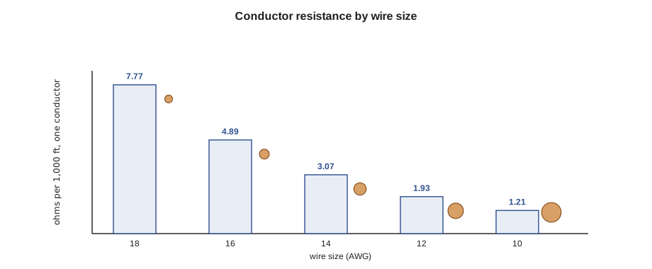
Stranded conductors have slightly more resistance than solid ones of the same gauge, and some fire alarm cables use stranded conductors for flexibility. The cable maker's data sheet gives the resistance to use. Some panel and appliance makers publish their own tables of maximum circuit lengths for each gauge, which are convenient but only valid for the loads and conditions they assume.
Temperature and resistance
Copper's resistance rises about 0.393 percent per degree Celsius above 68 °F. A cable in a hot attic or a boiler room, or one carrying enough current to warm itself, has more resistance than the table at 68 °F suggests. That is why many fire alarm calculations use a table at 167 °F, which builds in a margin for warm conditions. The difference between a 68 °F table and a 167 °F table is about 22 percent, which on a long notification circuit can be the difference between a design that works and one that does not.
# Conductor resistance of a two-wire circuit, corrected for temperature
ohm_per_kft_20C = {"18": 6.39, "16": 4.02, "14": 2.53, "12": 1.59}
alpha = 0.00393               # copper, per degree C
length = 500                # one-way, ft
for temp_c in (20, 40, 75):
    row = []
    for g in ("18", "16", "14", "12"):
        r = 2 * length * ohm_per_kft_20C[g] / 1000 * (1 + alpha * (temp_c - 20))
        row.append(f"{g} AWG {r:5.2f}")
print(f"{temp_c:3d} C: " + " ".join(row) + " ohm")20 C: 18 AWG 6.39 16 AWG 4.02 14 AWG 2.53 12 AWG 1.59 ohm 40 C: 18 AWG 6.89 16 AWG 4.34 14 AWG 2.73 12 AWG 1.71 ohm 75 C: 18 AWG 7.77 16 AWG 4.89 14 AWG 3.08 12 AWG 1.93 ohm
Choosing a conductor size
The minimum size of a fire alarm conductor is set by the electrical code and the equipment maker. The size actually used depends on the circuit. For initiating and signaling line circuits, current is small, so voltage drop is rarely the limit; the maker's limits on loop resistance and capacitance usually decide the maximum length, and 18 or 16 AWG is typical. For notification circuits, the current is large, and the voltage drop at the last appliance decides the size. The calculation is covered in lesson 9, but the principle is simple: choose the smallest wire that keeps the last appliance above its minimum listed voltage, with a margin, under worst-case conditions.
NFPA 70, the National Electrical Code, Article 760 sets the minimum conductor sizes and wiring methods for fire alarm systems, with power-limited circuits allowed down to 26 AWG in some cable types and non-power-limited circuits to 18 AWG; NFPA 72 and the panel maker's instructions may set further limits. Many designers keep a standard minimum such as 16 AWG for notification circuits regardless of calculation, to leave room for later additions.
A larger wire costs more, takes more space in conduit and is harder to terminate on small appliance terminals, so oversizing has real costs. Most notification appliances accept 18 to 12 AWG conductors; a 10 AWG conductor may need a junction box with a splice to a smaller pigtail at the appliance, which adds connections that can fail. When a circuit would need wire that large, it is usually better to split it into two circuits or add a remote power supply closer to the load.
Capacitance and signaling line circuits
Addressable signaling line circuits carry digital data, and for them the cable's capacitance and resistance together limit the length. Capacitance between the two conductors of a long cable slows the edges of the data pulses, and at some length the panel can no longer read the devices reliably. Panel makers publish maximum loop resistance and capacitance, often with a recommended cable such as twisted, shielded or unshielded pairs of a certain gauge. Installing the wrong cable, such as an untwisted pair for a loop that requires twisted, can produce intermittent communication faults that are hard to trace.
Terminations and connections
Every connection in a circuit adds a little resistance, and a poor connection can add a lot. A screw terminal that is loose, a conductor nicked during stripping, a wire nut that never gripped both conductors, a crimp made with the wrong tool: each can add ohms to a circuit that the calculation said would lose only a volt. Connections also change over time. They corrode in damp areas, loosen with vibration and heat cycling, and fail suddenly after years of working. Good practice in fire alarm work avoids unnecessary splices, uses listed connectors, keeps splices in accessible boxes, and torques terminals to the maker's value.
Fire alarm terminals are often designed for a single conductor, or for two of the same size. Doubling two conductors under a terminal designed for one is a common cause of intermittent faults. Where a circuit continues from one appliance to the next, the appliance's terminals usually have separate in and out positions, and using them properly also keeps the circuit supervised: removing the appliance breaks the circuit and causes a trouble, instead of leaving the downstream wiring connected and unsupervised.
Worked problem
Can the 16 gauge go on the dock wall?
At Cartwright, one of the dock-wall notification circuits runs 540 ft from a remote power supply to its last appliance, carrying 1.8 A in alarm. The calculation on the drawings assumed 14 AWG and showed 19.1 V at the last appliance when the battery is at 20.4 V. How much worse would 16 AWG be?
Show solution
- With 14 AWG at 3.07 Ω per 1,000 ft, the loop is 2 × 540 ft = 1,080 ft, or 3.32 Ω.
- Using a lumped load at the end, the 14 AWG drop is about 1.8 × 3.3 = 6.0 V, but the appliances are spread along the wall, so the designer's point-by-point drop is smaller, giving the 19.1 V on the drawings.
- 16 AWG has 4.89 / 3.07 = 1.59 times the resistance of 14 AWG.
- The drop would rise from 20.4 − 19.1 = 1.3 V to about 1.3 × 1.58 = 2.1 V, leaving about 18.3 V. That is still above 16 V, but the margin shrinks.
Answer: Gerry asks Ravi, who reruns the calculation and approves 16 AWG for that circuit with a note on the drawings. The decision belongs to the designer, and the drawings must match what is installed.
Wire size and the future of a system
A fire alarm system's wiring usually outlives its panel and devices. Panels are replaced every fifteen to twenty-five years, appliances are upgraded as standards change, but the cable in the walls may stay for fifty years. A conductor size chosen for today's appliances also has to serve tomorrow's, which may draw more current or need more voltage. This is one reason designers sometimes choose a gauge larger than the calculation requires: the extra copper is cheap compared with replacing cable inside finished walls when the building's next upgrade needs it.
The reverse also happens. When an older building's horn circuits are converted to horn-strobes, the existing wiring, sized decades ago for horns that drew a few tens of milliamps, now has to carry hundreds of milliamps for each strobe. At Willowbank School, the 1968 wing's notification circuits were 18 AWG, installed for bells. When those circuits were converted to strobes, every circuit had to be recalculated, and two had to be replaced with 14 AWG because the old wire could not deliver enough voltage to the end of the corridor. Reusing existing wiring is often possible, but it must be proven by calculation and by testing the cable's insulation, not assumed.
Cable that is reused must also still meet the current code for its location and type. Older cable may have been installed under rules that allowed methods no longer permitted, or may not be listed for the space it passes through after a renovation changed that space's use. The designer checks the existing cable's type from its jacket legend, and the technician tests it before it is reconnected.
Finally, the as-built drawings must record the actual conductor sizes and lengths. The next technician who adds an appliance, or the next designer who changes the system, depends on those records to know how much capacity a circuit has left. A drawing that shows 14 AWG where 16 AWG was actually installed will lead someone into a calculation that passes on paper and fails in the field.
Common mistakes
MistakeCalculating the resistance of the one-way length only.
InsteadCount both conductors: twice the one-way length.
MistakeSubstituting a smaller gauge because it is on the truck.
InsteadAny change in gauge needs the designer to recheck the calculation.
MistakeUsing a 68 °F resistance table for a cable in a hot space.
InsteadUse 167 °F values or correct for temperature.
MistakeTwisting two conductors under one terminal.
InsteadUse separate in and out terminals so the circuit stays supervised.
MistakeInstalling untwisted cable where the panel maker requires twisted pair.
InsteadFollow the maker's cable requirements for signaling line circuits.
Summary and key terms
- Resistance grows with length and falls with area: R = ρL/A.
- A two-wire circuit's conductor length is twice the one-way length.
- In AWG, larger numbers are smaller wires; three gauges halve or double the area.
- Copper's resistance rises about 0.4 percent per degree Celsius; tables at 167 °F build in margin.
- Notification circuits are sized by voltage drop; signaling line circuits by the maker's limits.
- Every connection adds resistance; avoid splices and double-terminated screws.
- AWG
- American Wire Gauge; larger numbers are smaller conductors.
- Resistivity
- A material's resistance per unit length and area.
- Loop length
- The total conductor length of a circuit, out and back.
- Temperature coefficient
- The change in resistance per degree of temperature.
- Stranded conductor
- A conductor made of many small wires twisted together.
- Capacitance
- The ability of a cable to store charge between its conductors, which limits data circuits.
Practice problems
Work each problem on paper first, then reveal the answer to check.
What is the loop resistance of 16 AWG for a circuit 650 ft long (one way)?
Show answer
About 6.4 Ω (2 × 650 ft × 4.89 Ω per 1,000 ft).
Roughly how does the resistance of 12 AWG compare with 18 AWG?
Show answer
About a quarter.
A cable's resistance is 4.0 Ω at 68 °F. About what is it at 140 °F?
Show answer
About 4.6 Ω.
Why should every change in conductor size go back to the designer?
Show answer
It changes the voltage drop and may push the last appliance below its minimum voltage.
Lesson quiz · 5 questions
Score 60% or more to complete this lesson.
Create a free account to save your progress, take quizzes and earn a certificate.