
FAT-130 · Lesson 3 of 12 · 20 min
Series and parallel circuits
Gerry starts the third evening with two spools of wire, a 24-volt bench supply and a handful of resistors. He wires three resistors one after another and asks Sasha to predict the current. Then he wires the same three side by side and asks again. 'Every fire alarm circuit is one of these two shapes, or a mix of them,' he says. 'Detectors on a conventional zone, strobes on a notification circuit, batteries in a cabinet: once you can see which shape you're looking at, you can calculate anything on it.' This lesson covers series and parallel circuits, how voltage and current divide in each, and where each shape appears in fire alarm systems.
Series circuits
In a series circuit, components are connected end to end so that there is only one path for current. The same current flows through every component. The voltage of the source is shared among them, each taking a share in proportion to its resistance, and the voltages across the components add up to the source voltage. The total resistance is the sum of the individual resistances.
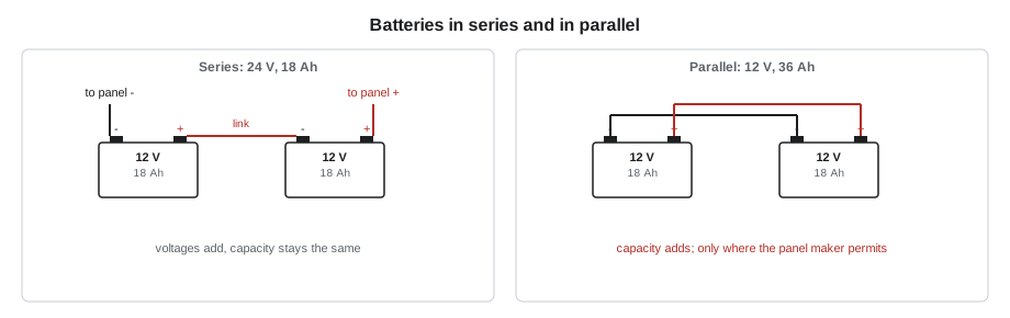
Series circuits appear in fire alarm work in a few important places. The two conductors of any circuit are in series with the load: current goes out along one and back along the other, so the resistance of both counts in a voltage drop calculation. An end-of-line resistor is in series with the circuit's conductors when the circuit is idle, which is how the panel measures the supervisory current. And batteries are connected in series to raise the voltage: two 12-volt batteries in series give 24 volts at the capacity of one battery.
The defining weakness of a series circuit is that a single break stops current everywhere. Old Christmas lights were wired this way, and one failed bulb darkened the string. Fire alarm supervision uses this property deliberately: a break anywhere in a supervised circuit stops the supervisory current, and the panel reports a trouble.
Parallel circuits
In a parallel circuit, components are connected across the same two points, so each has its own path for current. Every component sees the same voltage, and the total current is the sum of the currents in each branch. The total resistance is less than the smallest individual resistance, because adding a branch gives current another path.
Notification appliances on a circuit are connected in parallel across its two conductors: every strobe is connected from the positive conductor to the negative one, so each has the full circuit voltage available, minus whatever the wiring has dropped by the time the current reaches it, and the panel supplies the sum of all their currents. Detectors on a conventional initiating zone are connected the same way, in parallel across the pair, with the end-of-line resistor at the far end. When a detector alarms, it switches a low resistance across the pair, and the panel sees the current rise.
# Series and parallel resistance with Ohm's law
def series(*r): return sum(r)
def parallel(*r): return 1 / sum(1 / x for x in r)

V = 24.0
rs = (100, 200, 300)
Rs = series(*rs)
print(f"series: total {Rs:.0f} ohm, current {V / Rs * 1000:.0f} mA")
for r in rs:
    print(f"   {r:3d} ohm drops {V / Rs * r:5.1f} V")
Rp = parallel(*rs)
print(f"parallel: total {Rp:.1f} ohm, current {V / Rp * 1000:.0f} mA")
for r in rs:
print(f" {r:3d} ohm branch carries {V / r * 1000:5.0f} mA")series: total 600 ohm, current 40 mA 100 ohm drops 4.0 V 200 ohm drops 8.0 V 300 ohm drops 12.0 V parallel: total 54.5 ohm, current 440 mA 100 ohm branch carries 240 mA 200 ohm branch carries 120 mA 300 ohm branch carries 80 mA
Real circuits are a mix
A notification appliance circuit is a parallel circuit with series wiring. The appliances are in parallel, but the conductor segments between them are in series with each other: the current for the last appliance travels through every segment of wire from the panel, while the current for the first appliance travels only through the first segment. The first segment carries the current of every appliance on the circuit, the next segment carries the current of every appliance except the first, and so on. This is why voltage drops faster near the panel, where the current is highest, and why the last appliance sees the lowest voltage. Lesson 9 uses this structure to calculate voltage drop point by point.
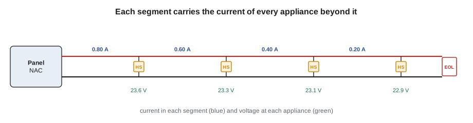
Branching a notification circuit is generally not allowed for supervised circuits: the wiring must run from appliance to appliance in a single path to the end-of-line device, so that the supervisory current passes through every conductor and a break anywhere is detected. A branch, or 'T-tap', would leave the wiring beyond the tap unsupervised. Signaling line circuits on addressable systems follow different rules, and some allow branches, as FAT-210 covers.
Batteries in series and in parallel
Fire alarm batteries are almost always 12-volt sealed lead-acid units, and the panel needs 24 volts, so they are installed in pairs in series. The voltages add, giving 24 volts nominal, and the capacity in amp-hours stays the same as one battery. Two 12-volt, 18 Ah batteries in series make a 24-volt, 18 Ah battery. Connecting batteries in parallel, positive to positive, keeps the voltage and adds the capacity, but most panel makers forbid paralleling batteries on their chargers, or allow it only with specific listed accessories, because a weaker battery in a parallel pair can be overcharged or drain its partner. Larger capacity comes from larger batteries or a listed external battery cabinet and charger.
Batteries in a series pair must be the same type, capacity and age. A new battery paired with a five-year-old one will be pushed unevenly by the charger, and the older one will limit the pair's capacity. When one battery in a pair fails a load test, both are replaced.
Kirchhoff's laws: checking your work
Two rules named after the physicist Gustav Kirchhoff give a quick check on any circuit calculation. The current law says that the current flowing into any junction equals the current flowing out: at each appliance on a notification circuit, the current arriving equals the appliance's current plus the current continuing down the line. The voltage law says that around any closed loop, the voltage rises equal the voltage drops: the panel's output equals the drop on the outgoing conductor, plus the voltage across the last appliance, plus the drop on the returning conductor. If a calculation doesn't satisfy both, something is wrong.
In the field, these laws turn into a troubleshooting method. If Sasha measures 24 volts at the panel and 20 volts at the last strobe in alarm, the 4 volts has gone somewhere in the wiring. Measuring the voltage at each appliance shows where it went: a steady fall along the circuit means the drop is shared by the wire, as expected, while a sudden step between two appliances points to a bad splice or terminal.
Shorts and opens
Two faults dominate fire alarm wiring, and both make sense in terms of series and parallel circuits. An open is a break in a conductor, which stops current in that path; on a series path, everything beyond the break loses power, and on a supervised circuit the supervisory current stops. A short is an unintended low-resistance path between conductors, which in parallel with everything else drops the total resistance to almost nothing and draws a large current. On a notification circuit, a short would draw enough current to trip the panel's circuit protection. On an idle supervised circuit, the panel detects the short because the supervisory current rises far above normal.
# How the panel sees an idle supervised circuit (illustrative values)
V = 24.0
EOL = 4700.0      # end-of-line resistor, ohms
wire = 12.0       # conductor resistance, ohms
cases = {
    "normal": wire + EOL,
    "open wire": float("inf"),
    "short at the far end": wire,
}
for name, R in cases.items():
    I = 0 if R == float("inf") else V / R * 1000
print(f"{name:22s} supervisory current {I:8.2f} mA")normal supervisory current 5.09 mA open wire supervisory current 0.00 mA short at the far end supervisory current 2000.00 mA
Worked problem
A conventional zone at Willowbank
Willowbank School's old 12-zone panel supervises each initiating zone with a 4.7 kΩ end-of-line resistor at 24 V. Zone 7 has 14 detectors in parallel and a total of 850 ft of 18 AWG wire. Each detector draws about 0.1 mA in standby. What does the panel see in normal standby, and what changes when a detector alarms?
Show solution
- The wire's loop resistance is small compared with 4,700 Ω, so the supervisory current through the resistor is about 24 / 4,700 = 5.1 mA.
- The detectors' standby current adds 14 × 0.1 = 1.4 mA, for a total of about 6.5 mA.
- When a detector alarms, it connects a low resistance, often a few hundred ohms including a current-limiting resistor, across the pair, in parallel with the end-of-line resistor.
- The current rises to tens of milliamps, which the panel reads as an alarm; a dead short would draw even more and is read as a short-circuit trouble on panels that can tell the difference.
Answer: The panel sorts the zone into normal, alarm or trouble by the current it measures. A technician who knows the expected current can measure the zone and know what the panel is seeing.
Series and parallel on a training board
Gerry's bench exercise ends with a test of intuition. He connects four 470-ohm resistors to the 24-volt supply in different arrangements and asks the trainees to predict the current each time before measuring it. In series, the total is 1,880 ohms and the current about 12.8 milliamps. In parallel, the total is 117.5 ohms and the current about 204 milliamps. With two pairs in parallel, connected in series with each other, the total is back to 470 ohms and the current 51 milliamps. The point of the exercise is not the arithmetic, which a calculator does, but the habit of predicting a reading before taking it. A technician who knows what the meter should show notices immediately when it shows something else.
The same habit applies on real systems. Before Sasha measures a conventional zone at Willowbank, she works out what the supervisory current should be from the panel's voltage and the end-of-line resistor's value. Before she clamps a notification circuit in alarm, she adds up the appliances' currents from the record drawings. When the reading matches, she moves on; when it doesn't, she knows something about the circuit is different from the drawings, and she has a starting point for finding out what.
Series and parallel thinking also explains why adding appliances to an existing circuit is never free. Each new appliance is another parallel branch, adding its current to every segment of wire between it and the panel. An appliance added near the far end of a long circuit adds its current to the whole length, and lowers the voltage at every appliance beyond the panel. That is why every addition goes back to the calculation, as lesson 9 shows.
One last pattern shows up in older buildings: circuits that have been extended over the years by tapping into the nearest junction box. A circuit that was installed as a single run can end up with branches that nobody drew. The supervisory current then passes through only one path to the end-of-line resistor, and the branches are unsupervised. Finding such branches, by comparing the measured loop resistance with the drawings and by tracing the wiring, is part of taking over an old system.
Common mistakes
MistakeBranching a supervised notification circuit with a T-tap.
InsteadRun supervised circuits in a single path to the end-of-line device.
MistakeForgetting that both conductors are in series with the load.
InsteadCount the resistance of the out and return conductors.
MistakePairing a new battery with an old one.
InsteadBatteries in a series pair must match in type, capacity and age.
MistakeConnecting batteries in parallel to add capacity.
InsteadDo it only where the panel's listing permits.
MistakeExpecting the voltage to be the same at every appliance on a circuit.
InsteadEach segment of wire drops voltage; the last appliance sees the least.
Summary and key terms
- In series, the current is the same everywhere and resistances add.
- In parallel, the voltage is the same across each branch and branch currents add.
- Notification appliances are in parallel, fed by wire segments in series.
- Two 12 V batteries in series make 24 V at the capacity of one.
- Kirchhoff's laws check calculations and guide troubleshooting.
- An open stops current; a short draws a large current.
- Series circuit
- A circuit with one path, where the same current flows through every component.
- Parallel circuit
- A circuit where components share the same two connection points and see the same voltage.
- T-tap
- A branch in a circuit; not allowed on supervised notification circuits.
- Open
- A break in a circuit that stops current.
- Short
- An unintended low-resistance connection between conductors.
- Kirchhoff's laws
- Rules that currents into a junction equal currents out, and voltages around a loop sum to zero.
Practice problems
Work each problem on paper first, then reveal the answer to check.
What is the total resistance of 150 Ω, 220 Ω and 330 Ω in series?
Show answer
700 Ω.
What is the total resistance of two 4.7 kΩ resistors in parallel?
Show answer
2.35 kΩ.
Four strobes on a circuit draw 0.18 A each. What current does the first segment of wire carry?
Show answer
0.72 A.
Two 12 V, 12 Ah batteries are connected in series. What voltage and capacity result?
Show answer
24 V and 12 Ah.
A panel measures 0 mA on an idle supervised zone. What fault is likely?
Show answer
An open in the circuit.
Lesson quiz · 5 questions
Score 60% or more to complete this lesson.
Create a free account to save your progress, take quizzes and earn a certificate.