
FAT-130 · Lesson 1 of 12 · 19 min
Electricity in fire alarm systems
Sasha Vukovic's second year at Bramwell Fire Protection starts in a classroom instead of a riser closet. Every Tuesday evening through the winter, Gerry Tremaine runs an electrical theory block for the trainees, and he opens it with a question he says he asks every apprentice. 'A fire alarm system has one job that nothing else in the building has,' he says. 'It has to work on the worst day the building will ever have. The power might be out. The wires might be in a fire. The panel has to know if anything is broken before that day comes. Everything in this course, every formula and every rule, is about making sure the electricity is there when the alarm needs it.' This lesson is the map for the course: where electricity enters a fire alarm system, where it goes, what it does when it gets there, and why the trade cares so much about circuits that most of the time carry only a few milliamps.
Why electrical theory matters to a fire alarm technician
Fire alarm systems are low-voltage systems, mostly running at 24 volts direct current, and they rarely carry enough current to hurt anyone. That can make electrical theory seem like a formality. It isn't. Most of the problems a technician spends a career solving are electrical: a strobe at the end of a long circuit that flashes weakly, a battery that passes its load test in the shop and dies after four hours in a blackout, a ground fault that comes and goes with the humidity, a trouble signal from a circuit that tests perfectly with a meter. Each of these has an electrical explanation, and a technician who understands voltage, current, resistance and power can find it in minutes. A technician who doesn't will replace parts until the problem goes away, or until it comes back on the day of a fire.
Electrical theory also sits underneath the design decisions the technician has to check. When Ravi Menon, Bramwell's designer, sends a set of drawings, they include notification appliance circuit calculations, a battery calculation and a wiring schedule. The technician who installs the system is expected to notice when the installed reality doesn't match the paper: a circuit run 40 percent longer than the drawing because a corridor was rerouted, extra strobes added during construction, a smaller wire gauge substituted because it was on the truck. Every one of those changes affects whether the last appliance gets enough voltage and whether the battery lasts long enough.
The parts of the system that use electricity
A fire alarm system has a control unit, often called the panel, at its center, with circuits running out to the field. The initiating side carries signals from smoke detectors, heat detectors, manual stations and sprinkler switches to the panel. On a conventional system these are initiating device circuits, each a pair of wires with an end-of-line device; on an addressable system they are signaling line circuits, a loop or branch that carries digital communication with every device. The notification side carries power out from the panel to horns, strobes and speakers. These notification appliance circuits carry far more current than the initiating side, because each strobe draws tens to hundreds of milliamps when it flashes, and a large circuit might carry two or three amps. Auxiliary circuits power relays, door holders, duct detector modules and annunciators.
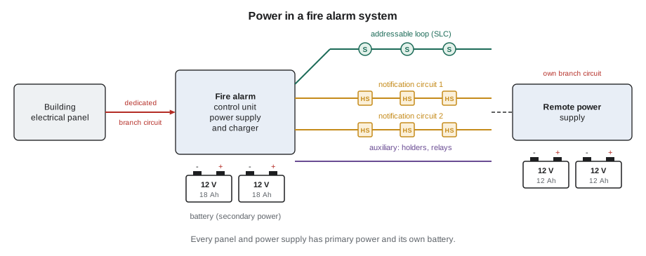
Each of these circuits has to be powered from somewhere, and in a fire alarm system that is never just a wall outlet. The panel and every remote power supply take their primary power from a dedicated branch circuit in the building's electrical system, and each has a secondary supply, almost always a set of sealed lead-acid batteries, that takes over automatically when the primary fails. The panel watches both. It reports a trouble if the primary power fails, if the battery is disconnected or low, or if the charger stops working.
Low voltage, but high consequence
Most fire alarm circuits run at a nominal 24 volts DC. That voltage is low enough that a technician working on field wiring is not usually at risk of a serious shock, and the circuits are classed as power-limited in most cases, which allows lighter cables and wiring methods than building power circuits. But the panel's primary supply is 120 volts AC, and in larger buildings the remote power supplies are fed from 120 or sometimes 240 volts. A technician who opens a panel or a power supply cabinet is working next to line voltage, and the lockout and safety practices from the safety lesson in FAT-110 apply.
The low voltage also makes the circuits sensitive. A 120-volt lighting circuit that loses 3 volts to wire resistance hardly notices; a 24-volt notification circuit that loses 3 volts has lost an eighth of its supply, and if the battery is already down to 20 volts at the end of a long blackout, that loss can push the last strobe below the voltage it needs to work. This is why fire alarm work has its own voltage drop calculations, and why they are done for the worst case: the battery at its lowest allowable voltage, at the end of its standby period, with every appliance on the circuit drawing its maximum current.
Supervision: a system that checks itself
The feature that makes fire alarm wiring different from almost every other kind of building wiring is supervision. The panel continuously monitors its own circuits for faults. An initiating circuit carries a small supervisory current through an end-of-line resistor, so the panel can tell the difference between a normal circuit, a broken wire, which stops the current, and a short, which raises it sharply. Notification circuits are monitored the same way while they are idle, with the panel reversing the polarity to power the appliances in alarm. Signaling line circuits are supervised by the communication itself: every device answers its poll, and a missing answer is a trouble. The panel also watches for ground faults, where any conductor touches the building's ground, because a ground fault can hide a second fault or make a circuit act unpredictably.
Supervision means that a fire alarm system tells you when it is broken. The trouble signal, a steady tone at the panel and a yellow indicator, is the system asking for a technician. Lesson 10 covers how supervision works electrically, and FAT-210 covers circuit classes and how panels report faults.
The units the trade works in
Fire alarm calculations use a small set of quantities, and a technician should be fluent with each of them. Voltage, measured in volts (V), is the electrical push that drives current. Current, measured in amps (A) or, for most fire alarm devices, milliamps (mA, thousandths of an amp), is the flow of charge. Resistance, measured in ohms (Ω), opposes current; wire has a small resistance that grows with length, and end-of-line resistors have a fixed resistance chosen by the panel's maker. Power, measured in watts (W), is the rate of using energy, and battery capacity is measured in amp-hours (Ah), the current a battery can supply for a given time. Lesson 2 builds the relationships among these quantities.
| Quantity | Unit | Typical fire alarm values |
|---|---|---|
| Voltage | volt (V) | 24 V DC nominal; 16 to 33 V operating range for listed 24 V appliances; 120 V AC primary |
| Current | amp (A), milliamp (mA) | smoke detector 0.05 to 0.3 mA standby; strobe 40 to 250 mA; panel 0.2 to 0.5 A standby |
| Resistance | ohm (Ω) | 18 AWG wire about 7.8 Ω per 1,000 ft; end-of-line resistors a few kilohms |
| Power | watt (W) | speaker taps 1/4 to 2 W; power supply outputs 50 to 200 W |
| Battery capacity | amp-hour (Ah) | 7, 12, 18, 26, 40 and 55 Ah common sizes |
# Converting between the units used in fire alarm work
standby_mA = [0.3, 0.3, 0.3, 0.3, 45.0]   # four detectors and a relay module, in mA
total_mA = sum(standby_mA)
print(f"total standby current: {total_mA:.1f} mA = {total_mA / 1000:.4f} A")
strobe_mA = 180
print(f"a strobe drawing {strobe_mA} mA draws {strobe_mA / 1000:.3f} A")
amps, hours = 0.5, 24
print(f"{amps} A for {hours} h uses {amps * hours:.1f} Ah of battery capacity")
volts, amps = 24, 2.5
print(f"{amps} A at {volts} V is {volts * amps:.0f} W")total standby current: 46.2 mA = 0.0462 A a strobe drawing 180 mA draws 0.180 A 0.5 A for 24 h uses 12.0 Ah of battery capacity 2.5 A at 24 V is 60 W
Where the electricity has to be on the worst day
Gerry draws a timeline on the whiteboard. A storm takes out the utility at 7 p.m. on a Friday. The building's generator, if it has one, may or may not start; many smaller buildings have no generator at all. The fire alarm system switches to its batteries and carries on supervising, drawing standby current all night and all of Saturday. At 6 p.m. on Saturday, a space heater set up by a resident starts a fire. The batteries now have to sound every horn and flash every strobe in the building, for long enough to get everyone out. The battery that was sized correctly does it; the one that was too small, or was never replaced after five years of service, fails at the moment it matters.
In the United States, NFPA 72 sets how long a fire alarm system's secondary power must last: typically 24 hours of standby followed by 5 minutes of alarm for a general evacuation system, or 15 minutes of alarm for an emergency voice system, with longer standby for some supervising station systems. Lessons 7 and 8 work through these requirements.
Electricity and the other trades
The fire alarm technician depends on the electrician for the system's primary power. The branch circuit that feeds the panel must be dedicated to the fire alarm system, with its breaker locked or identified so that nobody switches it off by mistake, and it is usually installed by the electrical contractor. When Sasha's crew starts work at a new building, one of the first things Gerry checks is the panel's branch circuit: the breaker label, the lock, the circuit's identification in the electrical panel's directory, and the voltage at the panel's terminals. A fire alarm system on a shared circuit with a coffee maker is a trouble waiting to happen.
The technician also has to coordinate with the electrician on the field wiring. In many projects the electrical contractor installs the conduit and pulls the fire alarm cable, and the fire alarm contractor terminates and tests it. Mistakes in that hand-off, such as a cable pulled through the wrong route, splices hidden in a ceiling, a notification circuit wired as a branch where the design called for a single run, become the fire alarm technician's problem at verification. Knowing the wiring rules in lesson 11 lets the technician catch them early.
Worked problem
Tamarind House: where does the power go?
Sasha is given the record drawings for Tamarind House, the six-story office building Bramwell maintains, and asked to list every point where the fire alarm system takes power from the building and every place that stores energy for it.
Show solution
- The main panel in the ground-floor electrical room is fed from a dedicated 15 A branch circuit, labeled 'FIRE ALARM' with a red breaker lock.
- The panel has two 18 Ah batteries in its cabinet.
- Two remote power supplies, on the third and fifth floors, drive the notification circuits for the upper floors. Each has its own dedicated branch circuit and its own pair of 12 Ah batteries.
- The annunciator in the lobby, the duct detector modules on the air handlers and the door holders on the stair doors all take power from the panel's auxiliary output, so their current counts against the panel's battery.
Answer: Three primary power connections and three battery sets. When Sasha checks them in the field, she finds the fifth-floor power supply's breaker is labeled only with a circuit number, which goes on the deficiency list.
Common mistakes
MistakeTreating 24 V fire alarm circuits as unimportant because they are low voltage.
InsteadA few volts lost on a 24 V circuit can stop the last appliance from working.
MistakeCalculating voltage drop with the battery fully charged.
InsteadUse the worst case: the battery at its lowest allowable voltage after the standby period.
MistakeForgetting the current drawn by auxiliary loads such as door holders and annunciators.
InsteadEverything powered by the panel counts against its battery.
MistakeAssuming the panel's branch circuit is dedicated without checking.
InsteadVerify the breaker, its label and its lock, and that nothing else is on it.
MistakeIgnoring a trouble signal that clears on its own.
InsteadIntermittent troubles are electrical clues; investigate them.
Summary and key terms
- Fire alarm systems mostly run at 24 V DC and must work on the worst day the building has.
- Initiating and signaling line circuits carry small currents; notification circuits carry much larger ones.
- Every panel and power supply has a dedicated primary circuit and a battery that takes over automatically.
- Supervision lets the panel detect opens, shorts and ground faults on its circuits.
- NFPA 72 sets 24 hours of standby followed by 5 minutes of alarm, or 15 minutes for voice systems.
- Voltage drop and battery calculations are done for the worst case.
- Primary power
- The normal supply to a fire alarm panel or power supply, from a dedicated branch circuit.
- Secondary power
- The battery or other supply that takes over automatically when primary power fails.
- Supervision
- Continuous monitoring of circuits and power so that faults are reported as troubles.
- Notification appliance circuit
- A circuit that powers horns, strobes or speakers.
- Signaling line circuit
- A circuit carrying digital communication between the panel and addressable devices.
- Milliamp
- One thousandth of an amp.
Practice problems
Work each problem on paper first, then reveal the answer to check.
A panel draws 0.35 A in standby. How many amp-hours does it use in 24 hours?
Show answer
8.4 Ah.
A strobe draws 115 mA. What is that in amps?
Show answer
0.115 A.
How long must an emergency voice system run in alarm after the standby period, under NFPA 72?
Show answer
15 minutes.
Name two kinds of circuit that leave a fire alarm panel.
Show answer
Initiating or signaling line circuits, and notification appliance circuits (also auxiliary circuits).
Lesson quiz · 5 questions
Score 60% or more to complete this lesson.
Create a free account to save your progress, take quizzes and earn a certificate.