
ENGG-130 · Lesson 8 of 12 · 32 min
Internal forces: shear and bending moment diagrams
Lessons 4 and 5 found the forces acting on a body from outside: support reactions and, in trusses, the axial forces carried by each two-force member. But a beam does not fail at its supports; it fails somewhere along its length, where the internal forces are too large for its cross-section. To choose the size of a beam, a shaft or a frame member, an engineer must know how the internal forces vary along it and where they are greatest. This lesson shows how to find the internal axial force, shear force and bending moment at any section by the method of sections, how to draw shear and bending moment diagrams for a whole beam, and how the simple relationships between load, shear and moment make those diagrams quick to sketch and check. These diagrams are the bridge between statics and the design of structural members in mechanics of materials.
Internal forces at a section
Imagine cutting a beam at some point. For each piece to stay in equilibrium, the material on one side of the cut must exert forces on the material on the other side. In a two-dimensional member, these internal forces reduce to three components at the cut:
- The normal (axial) force N, along the member's axis, tension or compression.
- The shear force V, perpendicular to the axis, which tends to slide one side of the cut past the other.
- The bending moment M, a couple that tends to bend the member.
By Newton's third law, the forces on the two faces of the cut are equal and opposite. To find them, cut the member, draw a free-body diagram of either piece including the unknown N, V and M at the cut, and apply the equilibrium equations. Choose the piece with fewer loads on it.
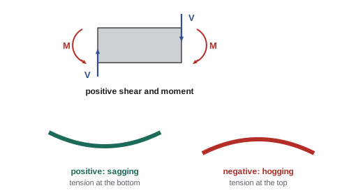
A sign convention is needed so that results from different sections can be compared. The usual convention in North American textbooks is: tension positive for N; shear positive when it pushes the left piece up (and the right piece down); and moment positive when it bends the member concave upward, called sagging, with compression on top and tension on the bottom. Negative moment, hogging, bends the member concave downward, as over a support or at a cantilever's root.
Worked problem
Internal forces at one section
A 6 m simply supported beam carries a 30 kN point load 2 m from the left support A. Find the shear and bending moment at a section 4 m from A.
Show solution
- Reactions: moments about A give \(6B_y = 30(2)\), so \(B_y = 10\) kN and \(A_y = 20\) kN.
- Cut at x = 4 m and take the right piece (2 m long), which carries only \(B_y\).
- Vertical equilibrium of the right piece: the shear on its left face plus \(B_y\) is zero. With the convention (shear on the right piece positive downward), \(V = -10\) kN.
- Moments about the cut, for the right piece: \(M = B_y \times 2 = 20\) kN·m, sagging (positive).
Answer: V = −10 kN and M = +20 kN·m. Using the left piece instead (A_y = 20 kN up and 30 kN down at 2 m) gives the same: V = 20 − 30 = −10 kN, M = 20(4) − 30(2) = 20 kN·m. Getting the same answer from both sides is a good check.
Shear and bending moment diagrams
Repeating the method of sections at a general position x gives V(x) and M(x) as functions, which are plotted below a sketch of the beam as the shear diagram and the moment diagram. Between loads, the functions are simple: constant or linear shear, linear or parabolic moment. Each change of loading starts a new segment, so a beam with point loads and partial distributed loads needs a separate expression for each region.
Worked problem
Simply supported beam with a uniform load
A simply supported beam of span L carries a uniform load w over its whole length. Find V(x) and M(x) and the maximum moment.
Show solution
- Reactions: by symmetry, each is wL/2.
- Cut at x and take the left piece: it carries the reaction wL/2 and a load wx acting at x/2.
- \[V(x) = \frac{wL}{2} - wx \qquad M(x) = \frac{wL}{2}x - \frac{wx^2}{2}\]
- The moment is greatest where its derivative, which is the shear, is zero: at x = L/2.
- \[M_{\max} = \frac{wL}{2}\cdot\frac{L}{2} - \frac{w}{2}\left(\frac{L}{2}\right)^2 = \frac{wL^2}{8}\]
Answer: The shear falls linearly from +wL/2 to −wL/2, crossing zero at midspan, and the moment is a parabola with its maximum wL²/8 at midspan. For the 8 m office floor beam of Lesson 7 (17.7 kN/m), \(M_{\max} = 17.7 \times 8^2/8 = 142\) kN·m at service loads, the number that, with a load factor, selects the steel section.
Relationships between load, shear and moment
Considering equilibrium of a tiny slice of beam of length dx, with distributed load w(x) acting downward, gives two relationships that make diagrams much faster to draw:
In words: the slope of the shear diagram equals minus the load intensity, and the slope of the moment diagram equals the shear. Integrating, the change in shear between two points equals minus the area of the load diagram between them, and the change in moment equals the area of the shear diagram between them. Point loads and couples, which act over zero length, cause jumps:
- A downward point force P makes the shear jump down by P.
- A concentrated couple M₀ makes the moment jump, up for a clockwise couple with the convention above.
Several practical rules follow. Where there is no distributed load, shear is constant and moment varies linearly. Under a uniform load, shear varies linearly and moment parabolically. The maximum moment occurs where the shear passes through zero (or at a point load, support or free end). At a free end or a pinned end without a couple, the moment is zero.
# Shear and bending moment along the overhanging beam of Lesson 4
# 8 m beam: pin at A (x = 0), roller at B (x = 6), 4 kN/m on A to B, 10 kN down at x = 8
w, P, xB, L = 4.0, 10.0, 6.0, 8.0
By = (w * xB * xB / 2 + P * L) / xB          # moments about A
Ay = w * xB + P - By
print(f"Reactions: Ay = {Ay:.2f} kN, By = {By:.2f} kN")

def V(x):                                     # shear at x (right of the support at B); positive when the left part is pushed up
    v = Ay - w * min(x, xB)
    if x >= xB:
        v += By
    return v

def M(x):                                     # bending moment at x (sagging positive)
    a = min(x, xB)
    m = Ay * x - w * a * (x - a / 2)
    if x > xB:
        m += By * (x - xB)
    return m

print("   x (m)   V (kN)   M (kN m)")
for x in [0, 1, 2, 3, 4, 5, 6, 7, 8]:
    print(f"{x:7.1f} {V(x):8.2f} {M(x):10.2f}")
x0 = Ay / w                                   # where the shear crosses zero
print(f"Shear is zero at x = {x0:.3f} m: maximum sagging moment {M(x0):.2f} kN m")
print(f"Moment over support B: {M(xB):.2f} kN m (hogging)")
xi = 2 * Ay / w                               # where M returns to zero between A and B
print(f"Point of inflection at x = {xi:.2f} m")Reactions: Ay = 8.67 kN, By = 25.33 kN
x (m) V (kN) M (kN m)
0.0 8.67 0.00
1.0 4.67 6.67
2.0 0.67 9.33
3.0 -3.33 8.00
4.0 -7.33 2.67
5.0 -11.33 -6.67
6.0 10.00 -20.00
7.0 10.00 -10.00
8.0 10.00 0.00
Shear is zero at x = 2.167 m: maximum sagging moment 9.39 kN m
Moment over support B: -20.00 kN m (hogging)
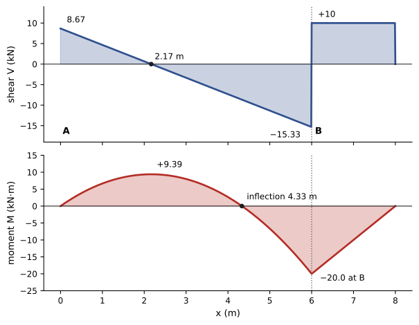
Point of inflection at x = 4.33 mThe output traces the diagrams for the beam of Lesson 4. Shear starts at +8.67 kN at A and falls at 4 kN/m, crossing zero at 2.17 m, where the moment peaks at +9.39 kN·m (sagging). The shear keeps falling to −15.33 kN just left of B, then jumps up by the 25.33 kN reaction to +10 kN, which stays constant along the unloaded overhang until the 10 kN load at the end brings it back to zero. The moment, after peaking, falls through zero at 4.33 m, a point of inflection where the beam changes from sagging to hogging, reaches −20 kN·m over support B, and rises linearly to zero at the free end. The largest moment in magnitude is the hogging moment over the support, not the sagging moment in the span.
Worked problem
Checking with areas
Use areas of the shear diagram to confirm the moment over support B in the overhanging beam.
Show solution
- From A to 2.17 m, the shear diagram is a triangle of height 8.67 and base 2.17: area \(+\tfrac{1}{2}(8.67)(2.17) = +9.39\).
- From 2.17 m to 6 m, a triangle of height −15.33 and base 3.83: area \(-\tfrac{1}{2}(15.33)(3.83) = -29.39\).
- Moment at B: \(0 + 9.39 - 29.39 = -20.0\) kN·m. ✓
- Along the overhang, the shear is +10 kN for 2 m: area +20, bringing the moment back to 0 at the free end. ✓
Answer: The area method confirms M_B = −20 kN·m and the zero moment at the free end. Closing to zero at a free end or a pin is the standard check that the diagrams are right.
Standard cases
A few cases occur so often that engineers know their results by heart, and design handbooks tabulate many more:
| Beam and load | Maximum shear | Maximum moment | Where |
|---|---|---|---|
| Simply supported, uniform load w over span L | wL/2 | wL²/8 | Midspan |
| Simply supported, point load P at midspan | P/2 | PL/4 | Midspan |
| Simply supported, point load P at a from left (b = L − a) | Pb/L (left) | Pab/L | Under the load |
| Cantilever, uniform load w over length L | wL | wL²/2 (hogging) | Fixed end |
| Cantilever, point load P at the tip | P | PL (hogging) | Fixed end |
Comparing them is instructive. A uniform load on a simply supported span produces half the maximum moment of the same total load concentrated at midspan (wL²/8 against PL/4 with P = wL). A cantilever with a uniform load has four times the maximum moment of the same beam simply supported. Superposition lets you add the diagrams for separate loads on the same beam, because statics is linear.
Worked problem
A cantilever balcony
A steel balcony beam cantilevers 1.8 m from a building. It carries a uniform load of 6.0 kN/m (deck, people and its own weight) and a 1.5 kN load at the tip from the railing. Find the maximum shear and moment.
Show solution
- Shear at the fixed end: \(6.0 \times 1.8 + 1.5 = 12.3\) kN.
- Moment at the fixed end: \(6.0 \times 1.8^2/2 + 1.5 \times 1.8 = 9.72 + 2.70 = 12.4\) kN·m (hogging).
Answer: V = 12.3 kN and M = −12.4 kN·m, both at the wall. A cantilever's moment and shear are greatest at the support, where the connection must transfer them into the building, which is why balcony connections, and the thermal breaks that stop them from becoming cold bridges, receive careful design. Balcony failures have usually started at deteriorated connections at the root.
Why the diagrams matter
Shear and moment diagrams tell a designer where a member is most heavily stressed and how much strength is needed along it. Bending stress in a beam is proportional to the bending moment divided by a property of the cross-section that depends on its second moment of area (Lesson 11); shear stress is proportional to the shear force. So the maximum moment usually sets a beam's depth and flange size, while the maximum shear, often near the supports, sets the web thickness and the connections. Reinforced concrete designers place tension steel on the side of the member where the moment diagram says tension occurs: at the bottom in sagging regions and at the top over supports, where hogging moment puts the top in tension. A beam with steel only in the bottom would crack at the top over an interior support. Points of inflection mark where the bars can change sides.
Members of frames carry axial force, shear and moment together, and the same method applies to each member, using the forces at its joints found by the methods of Lesson 5. In a portal frame or a crane jib, the moment diagram shows where the frame is stressed most, typically at the knees where beams meet columns.
Common mistakes
MistakeMixing sign conventions between sections.
InsteadAdopt one convention and apply it at every cut.
MistakeReplacing a distributed load by its resultant before cutting.
InsteadUse only the part of the load on the chosen side of the cut.
MistakeLooking for maximum moment only at midspan.
InsteadCheck where shear is zero, under point loads and over supports.
MistakeForgetting the jump in shear at a support reaction.
InsteadEvery point force, including reactions, makes the shear jump.
MistakeNot checking that the moment closes to zero at free and pinned ends.
InsteadUse the closure as a check on the whole diagram.
Summary and key terms
- At any section, a member carries axial force N, shear V and bending moment M, found by the method of sections.
- Positive shear pushes the left piece up; positive (sagging) moment puts the bottom in tension.
- dV/dx = −w and dM/dx = V; changes in V and M equal areas of the load and shear diagrams.
- Point loads make the shear jump; couples make the moment jump.
- Maximum moment occurs where shear is zero, at point loads or at supports.
- Standard results: wL²/8 and PL/4 for simple spans; wL²/2 and PL for cantilevers.
- Moment sets beam size and the side of concrete reinforcement; shear sets webs and connections.
- Internal forces
- Forces and moments transmitted across a section within a member.
- Normal force
- The internal force along a member's axis.
- Shear force
- The internal force perpendicular to a member's axis.
- Bending moment
- The internal couple that bends a member.
- Sagging
- Positive bending, concave upward, with tension on the bottom.
- Hogging
- Negative bending, concave downward, with tension on the top.
- Shear diagram
- A plot of shear force along a member.
- Moment diagram
- A plot of bending moment along a member.
- Point of inflection
- A point where the bending moment changes sign.
- Superposition
- Adding the effects of separate loads on a linear system.
Practice problems
Work each problem on paper first, then reveal the answer to check.
A 5 m simply supported beam carries 40 kN at midspan. Find the maximum shear and moment.
Show answer
20 kN; 40 × 5/4 = 50 kN·m.
A 6 m simply supported beam carries 12 kN/m. Find the maximum moment.
Show answer
12 × 36/8 = 54 kN·m.
A 6 m simply supported beam has 30 kN at 2 m from the left. Find the maximum moment.
Show answer
30 × 2 × 4/6 = 40 kN·m under the load.
A 2.5 m cantilever carries 8 kN/m. Find the shear and moment at the fixed end.
Show answer
20 kN; −25 kN·m.
If the shear over a 3 m length is constant at 15 kN, how much does the moment change?
Show answer
It increases by 45 kN·m.
What does a zero crossing in the shear diagram indicate?
Show answer
A maximum or minimum in the bending moment.
In the overhang example, what is the shear just left of B?
Show answer
8.67 − 24 = −15.33 kN.
Where should the main reinforcement go in a concrete beam over an interior support, and why?
Show answer
Near the top, because hogging moment puts the top in tension.
A simply supported 8 m beam carries 10 kN/m and a 20 kN point load at midspan. Find the maximum moment by superposition.
Show answer
80 + 40 = 120 kN·m.
Why is the hogging moment larger than the sagging moment in the overhang example?
Show answer
The 10 kN load on the 2 m overhang creates a 20 kN·m moment at B, which exceeds the span's sagging peak.
Lesson quiz · 5 questions
Score 60% or more to complete this lesson.
Create a free account to save your progress, take quizzes and earn a certificate.