
ENGG-130 · Lesson 7 of 12 · 42 min
Distributed loads and fluid pressure
Few real loads act at a single point. Snow lies across a whole roof; people, furniture and the floor itself spread their weight over a slab; wind presses on the face of a building or a sign; water and soil push on dams, tanks, gates and retaining walls; a beam's own weight runs along its length. Lesson 4 replaced a uniform and a triangular load by single forces to find reactions. This lesson develops that idea fully. It shows how to find the resultant of any distributed load and where it acts, how engineers turn floor and roof loads into loads on beams, and how to calculate the forces of fluids at rest on walls, gates and submerged bodies, including buoyancy. These calculations underlie the design of nearly every structure that holds back water or soil, and every beam that carries a floor.
Line loads and their resultants
A load spread along a beam is described by its intensity w(x), the force per unit length, in kN/m. The total force on a short length dx is w dx, so the resultant force is the integral of the intensity, which is the area under the load diagram. Its line of action, found by matching moments, passes through the centroid of that area (Lesson 6):
For the shapes that occur most often:
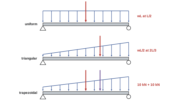
- A uniform load w over length L has resultant wL at the middle of the loaded length.
- A triangular load rising from zero to w over length L has resultant wL/2, one-third of the length from the high end (two-thirds from the zero end).
- A trapezoidal load is split into a rectangle and a triangle, each replaced by its own resultant.
Worked problem
A trapezoidal load
A 5 m beam carries a load that increases linearly from 2 kN/m at the left end to 6 kN/m at the right end. Find the resultant and its location.
Show solution
- Rectangle: 2 kN/m over 5 m gives 10 kN at 2.5 m from the left.
- Triangle: rising from 0 to 4 kN/m gives \(\tfrac{1}{2}(4)(5) = 10\) kN at \(\tfrac{2}{3}(5) = 3.33\) m from the left.
- Resultant: 20 kN. Location: \(\bar{x} = (10 \times 2.5 + 10 \times 3.33)/20 = 2.92\) m.
Answer: 20 kN acting 2.92 m from the left end, a little right of center because the load is heavier on the right. The resultant gives the correct reactions, but remember that it is an equivalent force for equilibrium of the whole body only: to find the internal forces at a section of the beam (Lesson 8), you must use the distributed load on the part of the beam on one side of the cut.
Worked problem
A load that varies as a parabola
A load on a 4 m member varies as \(w = 3x^2/4\) kN/m (x in meters), from zero at x = 0 to 12 kN/m at x = 4 m. Find the resultant and its location.
Show solution
- \[F_R = \int_0^4 \tfrac{3}{4}x^2\,dx = \tfrac{1}{4}x^3\Big|_0^4 = 16 \text{ kN}\]
- \[\int_0^4 x\cdot\tfrac{3}{4}x^2\,dx = \tfrac{3}{16}x^4\Big|_0^4 = 48 \text{ kN·m} \quad\Rightarrow\quad \bar{x} = 48/16 = 3.0 \text{ m}\]
Answer: 16 kN acting 3.0 m from the zero end, matching the parabolic spandrel in Lesson 6's table (3a/4 from the vertex).
From area loads to line loads
Building codes specify loads on floors and roofs as pressures, force per unit area, in kPa (kN/m²). A beam or joist collects the load from the floor area it supports, its tributary area. For a series of parallel beams, each one carries the strip of floor halfway to the beams on either side, a width called the tributary width. Multiplying the area load by the tributary width gives the line load on the beam.
ASCE 7, adopted through the International Building Code, specifies, for example, a live load of 40 psf (1.92 kPa) on residential floors, 50 psf (2.4 kPa) on office floors, and 100 psf (4.79 kPa) on assembly areas such as gyms and auditoriums, along with ground snow loads that depend on the site's climate. Dead loads come from the weights of the structure and permanent finishes. Designers combine them with load factors for strength design, such as 1.2 × dead + 1.6 × live.
Worked problem
Load on a floor beam
Steel floor beams in an office are spaced 3.0 m apart and span 8.0 m. The floor carries a dead load of 3.5 kPa (slab, finishes, ceiling and services) and a live load of 2.4 kPa. Find the service line load on an interior beam, the total load and the reactions.
Show solution
- Tributary width: halfway to each neighboring beam, 1.5 + 1.5 = 3.0 m.
- Area load: 3.5 + 2.4 = 5.9 kPa.
- Line load: \(w = 5.9 \times 3.0 = 17.7\) kN/m.
- Total: \(17.7 \times 8.0 = 142\) kN; by symmetry each end reaction is 71 kN.
Answer: A uniform 17.7 kN/m, 142 kN in total, with 71 kN at each support at service level. The same reactions then become point loads on the girders or columns that support the beams, so loads flow from slab to beam to girder to column to foundation, a path engineers trace through every building. Lesson 8 finds the internal shear and bending moment that size the beam itself.
Pressure in a fluid at rest
A fluid at rest cannot resist shear, so the force it exerts on any surface is perpendicular to that surface. Its pressure at a point is the same in all directions, and in a liquid of density ρ it increases linearly with depth h below the free surface:
For fresh water, ρg = 9.81 kN/m³, so pressure rises by 9.81 kPa for every meter of depth; seawater is about 3 % denser. Engineers usually work with gauge pressure, ignoring atmospheric pressure, because the atmosphere acts on both sides of most walls and gates and cancels out.
Because pressure grows linearly with depth, the load on a vertical wall is a triangle, and on a submerged surface whose top is below the water it is a trapezoid. The resultant force equals the volume of the pressure diagram, and it acts through that volume's centroid, called the center of pressure.
Worked problem
Water against a sluice gate
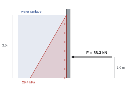
A vertical gate 2.0 m wide holds back water 3.0 m deep, with the water surface level with the top of the gate. Find the resultant water force and where it acts.
Show solution
- Pressure at the bottom: \(9.81 \times 3.0 = 29.4\) kPa; at the surface, zero.
- Force = area of the triangular pressure diagram times the width: \(F = \tfrac{1}{2}(29.4)(3.0)(2.0) = 88.3\) kN.
- It acts at the centroid of the triangle, one-third of the depth above the bottom: 1.0 m above the sill.
Answer: 88.3 kN, acting 1.0 m above the bottom (2.0 m below the surface). In general, for a vertical wall of width b holding water of depth h, the force is \(\tfrac{1}{2}\rho g h^2 b\): it grows with the square of the depth, so doubling the water depth quadruples the force and multiplies its overturning moment about the base by eight.
For any plane surface, vertical or inclined, the resultant force equals the pressure at the surface's centroid times its area, \(F = \rho g h_c A\), where \(h_c\) is the depth of the centroid. The center of pressure lies below the centroid, by an amount that depends on the area's second moment, a property introduced in Lesson 11. For rectangles, the trapezoidal pressure diagram gives the same result directly.
Worked problem
A fully submerged gate
A rectangular access gate 1.0 m wide and 1.5 m high is set in the vertical wall of a tank, with its top edge 2.0 m below the water surface. Find the force on the gate and where it acts.
Show solution
- Pressures: top \(9.81 \times 2.0 = 19.6\) kPa; bottom \(9.81 \times 3.5 = 34.3\) kPa.
- Split the trapezoid: rectangle \(19.6 \times 1.5 = 29.4\) kN/m at 0.75 m below the top; triangle \(\tfrac{1}{2}(14.7)(1.5) = 11.0\) kN/m at 1.0 m below the top. Width 1.0 m.
- Total: \(F = 40.5\) kN. Check: \(\rho g h_c A = 9.81 \times 2.75 \times 1.5 = 40.5\) kN. ✓
- Location below the top edge: \((29.4 \times 0.75 + 11.0 \times 1.0)/40.5 = 0.82\) m, that is, 2.82 m below the surface.
Answer: 40.5 kN acting 2.82 m below the surface, 0.07 m below the gate's centroid. The deeper a gate sits, the closer the center of pressure moves to the centroid, because the pressure becomes more nearly uniform over it. The gate's hinges and latches must be designed for these forces.
Retaining walls and dams
Walls that hold back water or soil must not slide or overturn. The horizontal force of the water tries to slide the wall along its base and to tip it about its downstream toe; the wall's weight, and friction at its base, resist. Concrete gravity dams are triangular or trapezoidal in section for exactly this reason: their width grows with depth to match the pressure.
Worked problem
Will the wall tip?
A vertical concrete wall (unit weight 24 kN/m³) is 4.0 m high and holds back water to its full height. Check overturning about the toe, per meter of wall, for thicknesses of 1.0 m and 2.0 m. Ignore uplift under the wall.
Show solution
- Water force: \(\tfrac{1}{2}(9.81)(4.0)^2 = 78.5\) kN/m at 1.33 m above the base. Overturning moment about the toe: \(78.5 \times 1.33 = 104.6\) kN·m/m.
- 1.0 m wall: weight \(24 \times 4.0 \times 1.0 = 96\) kN/m acting 0.5 m from the toe; resisting moment 48 kN·m/m. Less than 104.6: the wall overturns.
- 2.0 m wall: weight 192 kN/m acting 1.0 m from the toe; resisting moment 192 kN·m/m. Factor of safety \(192/104.6 = 1.84\).
Answer: A 1.0 m wall would tip over; a 2.0 m wall has a factor of safety against overturning of 1.84, above the 1.5 commonly required. Real designs must also check sliding, bearing pressure on the foundation, and uplift from water seeping under the base, which reduces the effective weight and has caused dam failures. Retaining walls for soil follow the same logic, with lateral earth pressure in place of water pressure, and they are usually built with a heel slab so that the weight of soil above it helps hold the wall down.
Curved surfaces
On a curved surface, the pressure acts perpendicular to every element, so the direction of force varies around the curve. It is easiest to find the horizontal and vertical components separately. The horizontal component equals the force on the vertical projection of the surface, calculated exactly as for a plane wall. The vertical component equals the weight of the water directly above the surface, up to the free surface (or, if the water is below the surface, the weight of the water that would fill that space, acting upward).
Worked problem
A radial gate
A quarter-circle gate of radius 2.0 m and width 3.0 m holds water that fills the quarter-circle space bounded by the gate, with the water surface level with the top of the gate. Find the components and resultant of the water force.
Show solution
- Horizontal: the vertical projection is 2.0 m high and 3.0 m wide: \(F_H = \tfrac{1}{2}(9.81)(2.0)^2(3.0) = 58.9\) kN.
- Vertical: the weight of the quarter circle of water: \(F_V = 9.81 \times \tfrac{\pi(2.0)^2}{4} \times 3.0 = 92.5\) kN.
- Resultant: \(\sqrt{58.9^2 + 92.5^2} = 109.6\) kN at \(\tan^{-1}(92.5/58.9) = 57.5°\) below the horizontal.
Answer: About 110 kN. Because every pressure force on a circular arc points toward the center of the circle, the resultant passes through the center, the location of the gate's pivot on a radial (Tainter) gate. The water therefore exerts almost no moment about the pivot, and a modest hoist can open a gate holding back enormous forces. Radial gates control the spillways of most large dams.
Buoyancy
A body immersed in a fluid experiences an upward buoyant force equal to the weight of the fluid it displaces (Archimedes' principle), \(F_B = \rho g V\), acting through the centroid of the displaced volume. Buoyancy explains why ships float and why submerged objects seem lighter. It also creates hazards: empty underground tanks, pipelines and manholes in high groundwater can float out of the ground, and engineers must anchor them.
Worked problem
An empty tank in wet ground
A fiberglass storage tank with an external volume of 10 m³ and a weight of 5 kN is buried in soil where the water table can rise to the surface. Find the net uplift on the empty tank, and the volume of concrete ballast (24 kN/m³, itself submerged) needed for a factor of safety of 1.2 against flotation.
Show solution
- Buoyancy on the tank: \(9.81 \times 10 = 98.1\) kN. Net uplift: \(98.1 - 5 = 93.1\) kN.
- Submerged concrete weighs \(24 - 9.81 = 14.2\) kN/m³ net.
- Required: \(5 + 14.2V_c = 1.2 \times 98.1\), so \(V_c = (117.7 - 5)/14.2 = 7.9\) m³ (ignoring soil above the tank, which also helps).
Answer: The empty tank would rise with a net force of about 93 kN, nine times its weight; about 8 m³ of concrete ballast, or straps to concrete deadmen, holds it down. Unanchored tanks have floated out of the ground after floods, and empty concrete pipes and manholes have popped up during construction when dewatering pumps stopped.
Wind pressure
Air in motion also exerts distributed pressure. The basic quantity is the velocity pressure \(q = \tfrac{1}{2}\rho V^2\), with air density ρ ≈ 1.25 kg/m³. The pressure on a surface is q times a pressure or drag coefficient that depends on the shape, about 1.2 to 2.0 for flat signs. At 100 km/h (27.8 m/s), q = 0.48 kPa; because pressure grows with the square of speed, a 140 km/h gust produces almost twice that. Building codes give reference wind pressures for each location and rules for coefficients, heights and gusts. A 3 m × 2 m road sign with a coefficient of 1.2 in a 100 km/h wind carries about 0.48 × 1.2 × 6 = 3.5 kN, acting at the center of the sign, which its posts and foundations must resist in bending and overturning.
Common mistakes
MistakePlacing a triangular load's resultant at mid-length.
InsteadIt acts at the centroid, one-third of the length from the high end.
MistakeUsing a distributed load's resultant to find internal forces at a section.
InsteadResultants work for the whole body; at a section, use only the load on one side of the cut.
MistakeUsing the full beam spacing on both sides when finding tributary width.
InsteadEach beam carries half the distance to each neighbor.
MistakePutting the hydrostatic resultant at the centroid of the wet surface.
InsteadIt acts at the center of pressure, below the centroid.
MistakeForgetting buoyancy and uplift on buried tanks and dams.
InsteadCheck flotation and uplift whenever groundwater can rise.
Summary and key terms
- A distributed load's resultant equals the area under the load diagram and acts at its centroid.
- Uniform: wL at the middle; triangular: wL/2 at one-third from the high end; split trapezoids.
- Area loads times tributary width give beam line loads; loads flow slab to beam to girder to column.
- Hydrostatic pressure p = ρgh acts perpendicular to surfaces and grows linearly with depth.
- On a plane surface, F = ρg h_c A, acting at the center of pressure below the centroid.
- On curved surfaces, find horizontal and vertical components separately.
- Buoyancy equals the weight of displaced fluid; check flotation of tanks and uplift on dams.
- Distributed load
- A load spread over a length or area, described by its intensity.
- Load intensity
- Force per unit length (kN/m) or per unit area (kPa).
- Tributary area
- The floor or roof area whose load a member supports.
- Tributary width
- The width of floor strip carried by a beam, half the distance to each neighbor.
- Hydrostatic pressure
- Pressure in a fluid at rest, ρgh in a liquid.
- Gauge pressure
- Pressure measured relative to atmospheric pressure.
- Center of pressure
- The point where the resultant fluid force on a surface acts.
- Gravity dam
- A dam that resists water pressure mainly by its own weight.
- Buoyant force
- The upward force on an immersed body, equal to the weight of displaced fluid.
- Velocity pressure
- Wind pressure ½ρV² used to calculate wind loads.
Practice problems
Work each problem on paper first, then reveal the answer to check.
A 6 m beam carries a uniform load of 5 kN/m. Find the resultant and its location.
Show answer
30 kN at 3 m.
A 3 m cantilever carries a triangular load from 8 kN/m at the wall to zero at the tip. Find the resultant and its distance from the wall.
Show answer
12 kN at 1.0 m from the wall.
Find the resultant of a load rising from 4 to 10 kN/m over 6 m and its distance from the light end.
Show answer
24 kN at 3 m and 18 kN at 4 m: 42 kN at 3.43 m.
Floor joists at 400 mm spacing carry 1.9 kPa live and 0.5 kPa dead load. Find the line load per joist.
Show answer
2.4 × 0.4 = 0.96 kN/m.
What is the gauge pressure at the bottom of a 12 m deep reservoir?
Show answer
9.81 × 12 = 118 kPa.
A vertical wall 5 m wide holds water 2 m deep. Find the force and its height above the base.
Show answer
½(9.81)(4)(5) = 98.1 kN at 0.67 m.
If the water in the previous question rises to 4 m, by what factor does the overturning moment about the base grow?
Show answer
8 (force × 4, lever arm × 2).
A 1 m wide, 2 m high vertical gate has its top 3 m below the surface. Find the force.
Show answer
9.81 × 4 × 2 = 78.5 kN.
What volume of concrete block (24 kN/m³) is needed to hold down an empty 2 m³, 1 kN tank with no safety factor, if the block is also submerged?
Show answer
(19.6 − 1)/14.2 = 1.31 m³.
Find the velocity pressure at 120 km/h.
Show answer
½(1.25)(33.3)² = 0.69 kPa.
Lesson quiz · 5 questions
Score 60% or more to complete this lesson.
Create a free account to save your progress, take quizzes and earn a certificate.