
ELEC-330 · Lesson 6 of 12 · 24 min
Programmable logic controller hardware
The programmable logic controller (PLC) was invented in the late 1960s to replace the banks of relays, timers and hard-wired logic that controlled automotive assembly lines, which had to be rewired every time a model changed. A PLC does the same job in software: it reads inputs from switches and sensors, executes a user program, and switches outputs to contactors, solenoids and lights, all in a rugged industrial package designed for electrical noise, vibration and temperature extremes. Today PLCs control everything from small packaging machines to entire water treatment plants and data center cooling systems, and they are increasingly networked with drives, HMIs and plant information systems. This lesson covers PLC architecture and form factors, the scan cycle, power supplies, discrete and analog input and output modules with their wiring, remote and distributed I/O, addressing, memory and program organization, panel installation and grounding, and how to select a PLC system.
Architecture and form factors
A PLC system consists of a processor (CPU) that executes the program and manages communications; input and output (I/O) modules that interface to field devices; a power supply; and communication interfaces. Form factors include:
- Nano and micro PLCs (sometimes called smart relays): small, fixed-I/O units with a few to a few dozen points, for simple machines.
- Compact PLCs: a CPU with built-in I/O and expansion modules, for small to medium machines.
- Modular PLCs: a chassis or backplane (rack) holding a power supply, CPU and many plug-in modules, for large machines and process systems, with options for redundant processors and hot-swappable modules.
- Distributed systems: a central controller with remote I/O stations over an industrial network (Lesson 10).
- Soft PLCs and industrial PCs that run control software on PC hardware, and programmable automation controllers (PACs), a term used for PLCs with PC-like capabilities.
PLC programming languages are standardized in IEC 61131-3 (Lesson 7), and PLC hardware requirements, including immunity and environmental tests, in IEC 61131-2.
The scan cycle
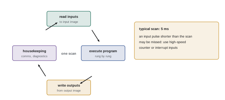
A PLC executes its program in a repeating cycle called the scan:
- Read inputs: copy the states of all inputs into an input image table in memory.
- Execute the program: solve the logic from top to bottom, using the input image and internal memory, writing results to an output image table.
- Write outputs: copy the output image to the physical outputs.
- Housekeeping: communications, diagnostics and other tasks.
Scan times range from under a millisecond to tens of milliseconds, depending on program size and processor speed. Because inputs are read once per scan, an input pulse shorter than the scan time can be missed entirely; fast events need high-speed counter inputs or interrupt inputs. Modern PLCs often also run multiple tasks at different rates (continuous, periodic and event tasks), with I/O updated asynchronously, which affects how programs must be written.
Discrete input modules
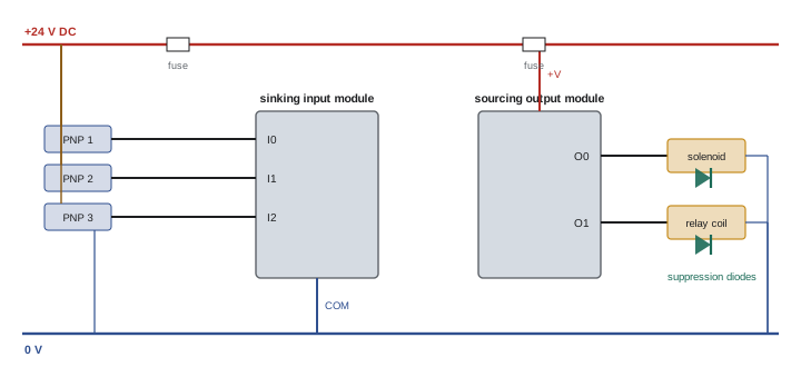
Discrete input modules convert field signals (24 V DC, 120 V AC and others) into logic states for the processor, with optoisolation (Lesson 1), filtering to reject contact bounce and noise, and status LEDs for each point. DC input modules are either sinking (current flows into the input, which connects to the common at 0 V, used with PNP sensors) or sourcing (current flows out of the input, with the common at +24 V, used with NPN sensors); some modules accept either, depending on how the common is wired. Input specifications include the on-state voltage and current, the off-state maximum (relevant to leakage from two-wire sensors and solid-state devices), filter time, and isolation between groups.
When a two-wire sensor's leakage current exceeds an input's off-state current, the input may read on or flicker. A bleeder (load) resistor across the input absorbs the leakage; its value is chosen so that leakage current flowing through it produces a voltage below the input's off-state limit.
Discrete output modules
Output modules switch field loads:
- Relay outputs: dry contacts that switch AC or DC loads at various voltages, with isolation between points; typically 2 A per point; slower and with limited mechanical life, but versatile.
- Transistor outputs: sourcing (PNP) or sinking (NPN) DC outputs, fast and long-lived, typically 0.5 to 2 A per point, for 24 V DC loads such as solenoids, indicators and relay coils.
- Triac outputs: for AC loads, with on-state drop and off-state leakage (Lesson 3).
Outputs have current ratings per point and per group or module, which must not be exceeded. Inductive loads need suppression to protect output transistors and triacs and to reduce noise, and some modules include it internally. Loads larger than the output rating are switched through interposing relays or contactors. Output circuits are protected by fuses or electronic protection; many transistor modules have built-in short-circuit protection and diagnostics.
Analog input and output modules
Analog input modules convert continuous signals (4–20 mA, 0–10 V, ±10 V, RTD, thermocouple) into numbers through an analog-to-digital converter. Resolution, typically 12 to 16 bits, determines the smallest change that can be detected: a 16-bit module divides its range into 65,536 steps. Modules may be single-ended (sharing a common) or differential (each input with its own reference, better for noise rejection), and current inputs may be loop-powered by the module or require external loop power (Lesson 5). Analog outputs (4–20 mA or 0–10 V) control valves, drive speed references and other proportional devices. The raw values from analog modules must be scaled to engineering units in the program (Lesson 9).
Worked problem
Resolution of an analog input
A 4–20 mA pressure transmitter ranged 0 to 1,000 kPa is connected to an analog input that converts 4–20 mA to integer values 0 to 32,000. What pressure does one count represent, and what count corresponds to 400 kPa?
Show solution
- Pressure per count: 1,000 kPa ÷ 32,000 = 0.03125 kPa per count.
- Count for 400 kPa: 400 ÷ 1,000 × 32,000 = 12,800.
- Corresponding current: 4 + 0.4 × 16 = 10.4 mA.
Answer: Each count is about 0.031 kPa, finer than the transmitter accuracy; 400 kPa reads 12,800 counts at 10.4 mA. Check each manufacturer's scaling, which varies.
Specialty modules
Other modules include high-speed counter modules for encoders and fast pulses, motion control modules for servo axes, temperature control modules with built-in PID, weighing modules for load cells, communication modules for additional networks and serial devices, and safety I/O modules for safety-rated controllers (Lesson 11).
Remote and distributed I/O
Instead of wiring every field device back to a central panel, remote I/O stations placed near the equipment connect to the controller over an industrial network. This reduces cable cost and installation time, shortens analog and low-voltage runs (reducing voltage drop and noise problems), and simplifies modifications. IP67-rated I/O blocks mount directly on machines without enclosures, connecting to sensors with M12 cordsets. Distributed I/O requires careful network design, addressing and documentation, and its behavior on communication loss (outputs off, hold last state, or a defined safe state) must be configured deliberately.
Addressing and memory
Each I/O point and memory location has an address the program uses. Older and some current PLCs use rack-slot-point or file-based addresses (for example I:1/3 or %IX1.3); modern systems use tag-based addressing, where the programmer gives each point and variable a descriptive name (Pump1_Running, Tank2_Level_HighHigh) mapped to physical I/O, which makes programs far easier to read and maintain. PLC memory holds the program, input and output images, internal bits, timers, counters, integers, floating-point values and data structures, with retentive memory that keeps values through power loss. Programs and configurations must be backed up and version controlled, because a lost or corrupted program can stop a plant for days.
Installation, power and grounding
PLC panels are installed following the manufacturer's instructions and the codes and standards for control panels (Lesson 3): adequate ventilation and spacing around modules for cooling, enclosure ratings suited to the environment, segregation of power and signal wiring, dedicated and protected power supplies, and proper grounding of the chassis and DIN rails. Many PLC problems that appear to be software faults are actually caused by poor power quality, noise, loose terminals or grounding problems. Field wiring is landed on terminal blocks rather than directly on modules where practical, so modules can be replaced quickly, and every wire is labeled at both ends to match the drawings.
Selecting a PLC system
Selection considers the number and types of I/O (with 10 % to 20 % spare), required speed and special functions (motion, high-speed counting, safety), communication networks needed to connect drives, HMIs and plant systems, environmental conditions, the plant's existing standards (spare parts, programming software and staff skills strongly favor staying with the same platform), vendor support and life cycle (how long the product will be manufactured and supported), and cybersecurity features. For critical processes, redundant processors, power supplies and networks may be required.
Commissioning PLC I/O
Before a PLC system controls a machine, every I/O point is checked from the field device to the program, a process often called an I/O check or point-to-point check. For each input, the device is operated (a sensor triggered, a switch actuated) and the corresponding input is verified on the module LED and in the program, with the correct tag. For each output, with the actuator safely isolated or the machine in a safe state, the output is turned on and the field device response checked. Analog inputs are checked by injecting known values with a calibrator and confirming the scaled reading at the HMI; analog outputs by setting values and measuring the signal at the field device.
Results are recorded on an I/O checklist, with any wiring errors, mislabeled tags or faulty devices corrected and rechecked. Thorough I/O checks find most installation errors before they cause problems during start-up, when time pressure is highest and mistakes can damage equipment.
The same systematic approach applies when modules are replaced: verify the module type and configuration, check that wiring has been reconnected to the right terminals, and test every point before returning the machine to production.
Spare parts and life cycle
PLC systems often stay in service for twenty years or more, far longer than the manufacturer produces the specific models. Plants maintain spare processors, power supplies and I/O modules for critical systems, with programs and firmware versions recorded so a spare can be loaded quickly. When products are announced as discontinued, plants plan migrations to current platforms before spares run out, a process that involves converting programs, replacing hardware and rewiring, and that benefits greatly from accurate documentation of the existing system.
In short, PLC hardware succeeds when it is selected with margin, installed carefully, checked point by point, and supported by spares and records for its whole life.
Common mistakes
MistakeExpecting a PLC to catch pulses shorter than its scan.
InsteadUse high-speed counter or interrupt inputs.
MistakeIgnoring leakage from two-wire sensors on PLC inputs.
InsteadCheck off-state current and add a bleeder resistor if needed.
MistakeDriving large loads directly from output points.
InsteadRespect point and group ratings; use interposing relays.
MistakeLeaving remote I/O loss-of-communication behavior at defaults.
InsteadConfigure a deliberate safe state.
MistakeKeeping no backup of PLC programs.
InsteadBack up and version control programs and configurations.
Summary and key terms
- PLCs replace relay logic with a processor, I/O modules, power supply and communications.
- Form factors range from smart relays to modular, redundant and distributed systems.
- The scan reads inputs, executes logic and writes outputs; short pulses can be missed.
- Discrete inputs are sinking or sourcing; outputs are relay, transistor or triac with current limits.
- Analog modules convert signals with 12 to 16-bit resolution; values need scaling.
- Remote I/O reduces wiring but needs network design and safe communication-loss behavior.
- Tag addressing, backups, proper installation and platform standards support reliable systems.
- PLC
- Programmable logic controller.
- Scan cycle
- The repeating read-execute-write sequence of a PLC.
- Input image table
- Memory holding input states for the current scan.
- Sinking input
- An input into which current flows from a sourcing device.
- Relay output
- An output with isolated dry contacts.
- Interposing relay
- A relay used to switch loads beyond an output rating.
- Resolution
- The number of steps an analog converter uses.
- Remote I/O
- I/O modules located near equipment and networked to the controller.
- Tag-based addressing
- Naming I/O and memory with descriptive tags.
- Retentive memory
- Memory that keeps values through power loss.
Practice problems
Work each problem on paper first, then reveal the answer to check.
Why were PLCs invented?
Show answer
To replace hard-wired relay logic that was costly to change.
List the steps of the scan cycle.
Show answer
Read inputs, execute program, write outputs, housekeeping.
A 3 ms pulse arrives with a 10 ms scan. What may happen?
Show answer
The PLC may miss it.
A sinking input module is used with which sensor type?
Show answer
PNP (sourcing) sensors.
Name three discrete output types.
Show answer
Relay, transistor and triac.
How many steps does a 12-bit converter have?
Show answer
4,096.
A 0–500 °C input scaled 0 to 32,000 reads 9,600. What is the temperature?
Show answer
150 °C.
Give two benefits of remote I/O.
Show answer
Less cable, shorter analog runs, easier changes.
Why are tag names preferred?
Show answer
They make programs readable and maintainable.
Name four PLC selection factors.
Show answer
I/O count, speed, networks, environment, plant standards, life cycle, security.
Lesson quiz · 5 questions
Score 60% or more to complete this lesson.
Create a free account to save your progress, take quizzes and earn a certificate.